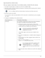
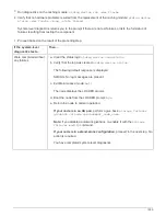
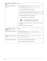
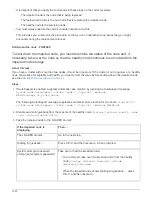
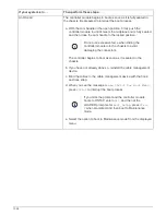
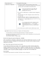
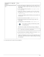

If your system is running
ONTAP…
Then…
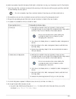
Resulted in some test failures
Determine the cause of the problem.
a. Exit Maintenance mode:
halt
b. Perform a clean shutdown, and then disconnect the power
supplies.
c. Verify that you have observed all of the considerations identified
for running system-level diagnostics, that cables are securely
connected, and that hardware components are properly installed
in the storage system.
d. Reconnect the power supplies, and then power on the storage
system.
e. Rerun the system-level diagnostics test.
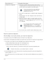
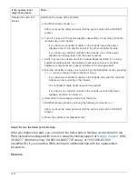
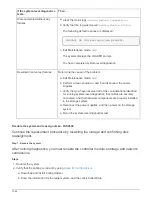
Step 3: Return the failed part to NetApp
After you replace the part, you can return the failed part to NetApp, as described in the
RMA instructions shipped with the kit. Contact technical support at
, 888-
463-8277 (North America), 00-800-44-638277 (Europe), or +800-800-80-800
(Asia/Pacific) if you need the RMA number or additional help with the replacement
procedure.
Controller module
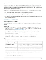
Replace the controller module - FAS2600
You must review the prerequisites for the replacement procedure and select the correct
one for your version of the ONTAP operating system.
• All drive shelves must be working properly.
• If your system is in an HA pair, the healthy node must be able to take over the node that is being replaced
(referred to in this procedure as the “impaired node”).
• This procedure includes steps for automatically or manually reassigning drives to the
replacement
node,
depending on your system’s configuration.
You should perform the drive reassignment as directed in the procedure.
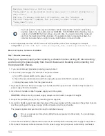
• You must replace the failed component with a replacement FRU component you received from your
provider.
• You must be replacing a controller module with a controller module of the same model type. You cannot
upgrade your system by just replacing the controller module.
• You cannot change any drives or drive shelves as part of this procedure.
• In this procedure, the boot device is moved from the impaired node to the
replacement
node so that the
replacement
node will boot up in the same version of ONTAP as the old controller module.
1049
Summary of Contents for AFF A700
Page 4: ...AFF and FAS System Documentation 1...
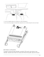
Page 208: ...3 Close the controller module cover and tighten the thumbscrew 205...
Page 248: ...2 Close the controller module cover and tighten the thumbscrew 245...
Page 308: ...Power supply Cam handle release latch Power and Fault LEDs Cam handle 305...
Page 381: ...Power supply Cam handle release latch Power and Fault LEDs Cam handle 378...
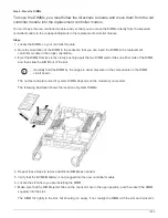
Page 437: ...1 Locate the DIMMs on your controller module 434...
Page 605: ...602...
Page 1117: ...3 Close the controller module cover and tighten the thumbscrew 1114...
Page 1157: ...2 Close the controller module cover and tighten the thumbscrew 1154...
Page 1228: ...Power supply Cam handle release latch Power and Fault LEDs Cam handle 1225...
Page 1300: ...Power supply Cam handle release latch Power and Fault LEDs Cam handle 1297...
Page 1462: ...Installing SuperRail to round hole four post rack 1459...
Page 1602: ...1599...
Page 1630: ...1627...
Page 1634: ...Orange ring on horizontal bracket Cable chain 1631...
Page 1645: ...Guide rail 1642...
Page 1669: ...Attention LED light on 1666...