
Option 2: Manually reassign the system ID on a stand-alone system in ONTAP
In a stand-alone system, you must manually reassign disks to the new controller’s system
ID before you return the system to normal operating condition.
About this task
This procedure applies only to systems that are in a stand-alone configuration.
Steps
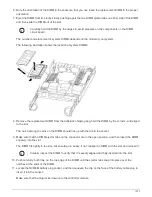
1. If you have not already done so, reboot the
replacement
node, interrupt the boot process by pressing Ctrl-
C, and then select the option to boot to Maintenance mode from the displayed menu.
2. You must enter Y when prompted to override the system ID due to a system ID mismatch.
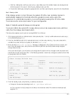
3. View the system IDs: disk show -a
4. You should make a note of the old system ID, which is displayed as part of the disk owner column.
The following example shows the old system ID of 118073209:
*> disk show -a
Local System ID: 118065481
DISK OWNER POOL SERIAL NUMBER HOME
-------- ------------- ----- ------------- -------------
disk_name system-1 (118073209) Pool0 J8XJE9LC system-1
(118073209)
disk_name system-1 (118073209) Pool0 J8Y478RC system-1
(118073209)
.
.
.
5. Boot the node:
boot_ontap
Complete system restoration - FAS2600
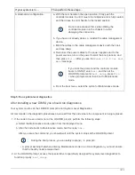
Step 1: Install licenses for the
replacement
node in ONTAP
You must install new licenses for the
replacement
node if the impaired node was using
ONTAP features that require a standard (node-locked) license. For features with standard
licenses, each node in the cluster should have its own key for the feature.
About this task
Until you install license keys, features requiring standard licenses continue to be available to the
replacement
node. However, if the impaired node was the only node in the cluster with a license for the feature, no
configuration changes to the feature are allowed. Also, using unlicensed features on the node might put you
out of compliance with your license agreement, so you should install the replacement license key or keys on
the
replacement
node as soon as possible.
1067
Summary of Contents for AFF A700
Page 4: ...AFF and FAS System Documentation 1...
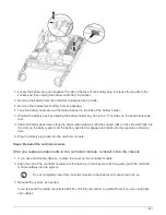
Page 208: ...3 Close the controller module cover and tighten the thumbscrew 205...
Page 248: ...2 Close the controller module cover and tighten the thumbscrew 245...
Page 308: ...Power supply Cam handle release latch Power and Fault LEDs Cam handle 305...
Page 381: ...Power supply Cam handle release latch Power and Fault LEDs Cam handle 378...
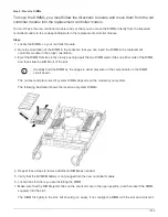
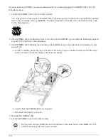
Page 437: ...1 Locate the DIMMs on your controller module 434...
Page 605: ...602...
Page 1117: ...3 Close the controller module cover and tighten the thumbscrew 1114...
Page 1157: ...2 Close the controller module cover and tighten the thumbscrew 1154...
Page 1228: ...Power supply Cam handle release latch Power and Fault LEDs Cam handle 1225...
Page 1300: ...Power supply Cam handle release latch Power and Fault LEDs Cam handle 1297...
Page 1462: ...Installing SuperRail to round hole four post rack 1459...
Page 1602: ...1599...
Page 1630: ...1627...
Page 1634: ...Orange ring on horizontal bracket Cable chain 1631...
Page 1645: ...Guide rail 1642...
Page 1669: ...Attention LED light on 1666...


