


The following AutoSupport message suppresses automatic case creation for two hours:
cluster1:*>
system node autosupport invoke -node * -type all -message MAINT=2h
2. Disable automatic giveback from the console of the healthy node:
storage failover modify –node
local -auto-giveback false
3. Take the impaired node to the LOADER prompt:
If the impaired node is
displaying…
Then…
The LOADER prompt
Go to the next step.
Waiting for giveback…
Press Ctrl-C, and then respond
y
when prompted.
System prompt or password
prompt (enter system password)
Take over or halt the impaired node:
• For an HA pair, take over the impaired node from the healthy
node:
storage failover takeover -ofnode
impaired_node_name
When the impaired node shows Waiting for giveback…, press
Ctrl-C, and then respond
y
.
Move and replace hardware - AFF A220 and FAS2700
Step 1: Move a power supply
Moving out a power supply when replacing a chassis involves turning off, disconnecting,
and removing the power supply from the old chassis and installing and connecting it on
the replacement chassis.
1. If you are not already grounded, properly ground yourself.
2. Turn off the power supply and disconnect the power cables:
a. Turn off the power switch on the power supply.
b. Open the power cable retainer, and then unplug the power cable from the power supply.
c. Unplug the power cable from the power source.
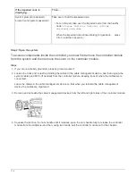
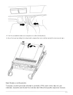
3. Squeeze the latch on the power supply cam handle, and then open the cam handle to fully release the
power supply from the mid plane.
4. Use the cam handle to slide the power supply out of the system.
CAUTION:
When removing a power supply, always use two hands to support its weight.
5. Repeat the preceding steps for any remaining power supplies.
6. Using both hands, support and align the edges of the power supply with the opening in the system chassis,
and then gently push the power supply into the chassis using the cam handle.
The power supplies are keyed and can only be installed one way.
125
Summary of Contents for AFF A700
Page 4: ...AFF and FAS System Documentation 1...
Page 208: ...3 Close the controller module cover and tighten the thumbscrew 205...
Page 248: ...2 Close the controller module cover and tighten the thumbscrew 245...
Page 308: ...Power supply Cam handle release latch Power and Fault LEDs Cam handle 305...
Page 381: ...Power supply Cam handle release latch Power and Fault LEDs Cam handle 378...
Page 437: ...1 Locate the DIMMs on your controller module 434...
Page 605: ...602...
Page 1117: ...3 Close the controller module cover and tighten the thumbscrew 1114...
Page 1157: ...2 Close the controller module cover and tighten the thumbscrew 1154...
Page 1228: ...Power supply Cam handle release latch Power and Fault LEDs Cam handle 1225...
Page 1300: ...Power supply Cam handle release latch Power and Fault LEDs Cam handle 1297...
Page 1462: ...Installing SuperRail to round hole four post rack 1459...
Page 1602: ...1599...
Page 1630: ...1627...
Page 1634: ...Orange ring on horizontal bracket Cable chain 1631...
Page 1645: ...Guide rail 1642...
Page 1669: ...Attention LED light on 1666...