
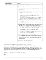
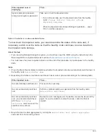
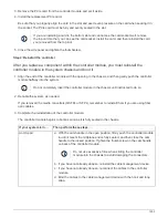


If your system is in…
Then perform these steps…
A two-node MetroCluster
configuration
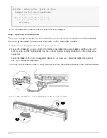
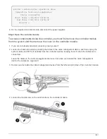
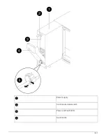
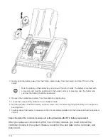
a. With the cam handle in the open position, firmly push the controller module
in until it meets the midplane and is fully seated, and then close the cam
handle to the locked position. Tighten the thumbscrew on the cam handle
on back of the controller module.
Do not use excessive force when sliding the controller
module into the chassis to avoid damaging the connectors.
b. If you have not already done so, reinstall the cable management device.
c. If you have not already done so, reconnect the cables to the controller
module.
d. Bind the cables to the cable management device with the hook and loop
strap.
e. Reconnect the power cables to the power supplies and to the power
sources, and then turn on the power to start the boot process.
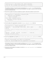
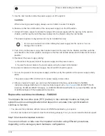
4. If your system is configured to support 10 GbE cluster interconnect and data connections on 40 GbE NICs
or onboard ports, convert these ports to 10 GbE connections by using the nicadmin convert command from
Maintenance mode.
Be sure to exit Maintenance mode after completing the conversion.
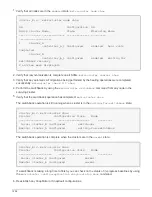
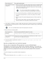
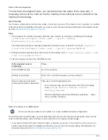
5. Return the node to normal operation:
If your system is in…
Issue this command from the partner’s console…
An HA pair
storage failover giveback -ofnode
impaired_node_name
A two-node MetroCluster
configuration
Proceed to the next step. The MetroCluster switchback procedure is done in
the next task in the replacement process.
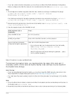
6. If automatic giveback was disabled, reenable it:
storage failover modify -node local -auto
-giveback true
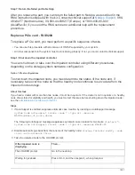
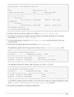
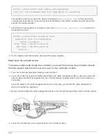
Step 5 (two-node MetroCluster only): Switch back aggregate
After you have completed the FRU replacement in a two-node MetroCluster
configuration, you can perform the MetroCluster switchback operation. This returns the
configuration to its normal operating state, with the sync-source storage virtual machines
(SVMs) on the formerly impaired site now active and serving data from the local disk
pools.
This task only applies to two-node MetroCluster configurations.
Steps
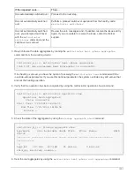
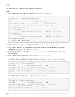
1. Verify that all nodes are in the
enabled
state:
metrocluster node show
1294
Summary of Contents for AFF A700
Page 4: ...AFF and FAS System Documentation 1...
Page 208: ...3 Close the controller module cover and tighten the thumbscrew 205...
Page 248: ...2 Close the controller module cover and tighten the thumbscrew 245...
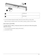
Page 308: ...Power supply Cam handle release latch Power and Fault LEDs Cam handle 305...
Page 381: ...Power supply Cam handle release latch Power and Fault LEDs Cam handle 378...
Page 437: ...1 Locate the DIMMs on your controller module 434...
Page 605: ...602...
Page 1117: ...3 Close the controller module cover and tighten the thumbscrew 1114...
Page 1157: ...2 Close the controller module cover and tighten the thumbscrew 1154...
Page 1228: ...Power supply Cam handle release latch Power and Fault LEDs Cam handle 1225...
Page 1300: ...Power supply Cam handle release latch Power and Fault LEDs Cam handle 1297...
Page 1462: ...Installing SuperRail to round hole four post rack 1459...
Page 1602: ...1599...
Page 1630: ...1627...
Page 1634: ...Orange ring on horizontal bracket Cable chain 1631...
Page 1645: ...Guide rail 1642...
Page 1669: ...Attention LED light on 1666...


