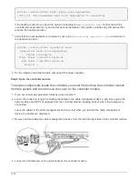
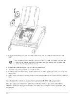

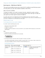

Power cable locking mechanism
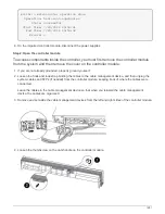
5. Use the cam handle to slide the power supply out of the system.
CAUTION:
When removing a power supply, always use two hands to support its weight.
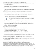
6. Make sure that the on/off switch of the new power supply is in the Off position.
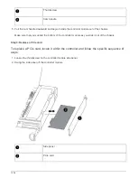
7. Using both hands, support and align the edges of the power supply with the opening in the system
chassis, and then gently push the power supply into the chassis using the cam handle.
The power supplies are keyed and can only be installed one way.
Do not use excessive force when sliding the power supply into the system. You can
damage the connector.
8. Push firmly on the power supply cam handle to seat it all the way into the chassis, and then push the
cam handle to the closed position, making sure that the cam handle release latch clicks into its locked
position.
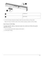
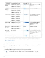
9. Reconnect the power supply cabling:
a. Reconnect the power cable to the power supply and the power source.
b. Secure the power cable to the power supply using the power cable retainer.
Once power is restored to the power supply, the status LED should be green.
1. Turn on the power to the new power supply, and then verify the operation of the power supply activity
LEDs.
The power supply LEDs are lit when the power supply comes online.
2. After you replace the part, you can return the failed part to NetApp, as described in the RMA
instructions shipped with the kit. Contact technical support at
, 888-463-8277 (North
America), 00-800-44-638277 (Europe), or +800-800-80-800 (Asia/Pacific) if you need the RMA number
or additional help with the replacement procedure.
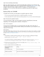
Replace the real-time clock battery - FAS8200
You replace the real-time clock (RTC) battery in the controller module so that your
system’s services and applications that depend on accurate time synchronization
continue to function.
• You can use this procedure with all versions of ONTAP supported by your system
• All other components in the system must be functioning properly; if not, you must contact technical support.
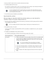
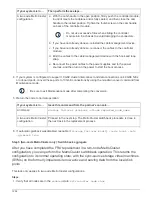
Step 1: Shut down the impaired controller
You can shut down or take over the impaired controller using different procedures,
depending on the storage system hardware configuration.
1298
Summary of Contents for AFF A700
Page 4: ...AFF and FAS System Documentation 1...
Page 208: ...3 Close the controller module cover and tighten the thumbscrew 205...
Page 248: ...2 Close the controller module cover and tighten the thumbscrew 245...
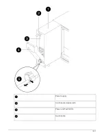
Page 308: ...Power supply Cam handle release latch Power and Fault LEDs Cam handle 305...
Page 381: ...Power supply Cam handle release latch Power and Fault LEDs Cam handle 378...
Page 437: ...1 Locate the DIMMs on your controller module 434...
Page 605: ...602...
Page 1117: ...3 Close the controller module cover and tighten the thumbscrew 1114...
Page 1157: ...2 Close the controller module cover and tighten the thumbscrew 1154...
Page 1228: ...Power supply Cam handle release latch Power and Fault LEDs Cam handle 1225...
Page 1300: ...Power supply Cam handle release latch Power and Fault LEDs Cam handle 1297...
Page 1462: ...Installing SuperRail to round hole four post rack 1459...
Page 1602: ...1599...
Page 1630: ...1627...
Page 1634: ...Orange ring on horizontal bracket Cable chain 1631...
Page 1645: ...Guide rail 1642...
Page 1669: ...Attention LED light on 1666...


