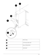
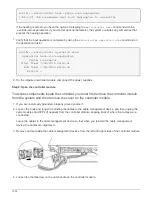
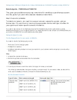
3. Attach cable management devices (as shown).
4. Place the bezel on the front of the system.
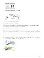
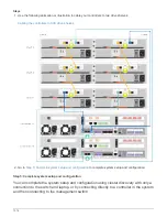
Step 3: Cable controllers to your network
You can cable the controllers to your network by using the two-node switchless cluster
method or by using the cluster interconnect network.
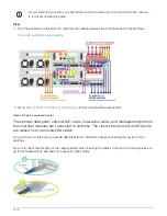
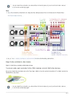
Option 1: Cable a two-node switchless cluster
The optional data ports, optional NIC cards, and management ports on the controller
modules are connected to switches. The cluster interconnect and HA ports are cabled on
both controller modules.
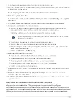
You must have contacted your network administrator for information about connecting the system to the
switches.
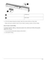
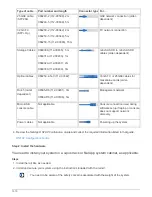
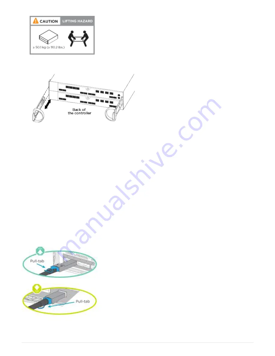
Be sure to check the direction of the cable pull-tabs when inserting the cables in the ports. Cable pull-tabs are
up for all onboard ports and down for expansion (NIC) cards.
1311
Summary of Contents for AFF A700
Page 4: ...AFF and FAS System Documentation 1...
Page 208: ...3 Close the controller module cover and tighten the thumbscrew 205...
Page 248: ...2 Close the controller module cover and tighten the thumbscrew 245...
Page 308: ...Power supply Cam handle release latch Power and Fault LEDs Cam handle 305...
Page 381: ...Power supply Cam handle release latch Power and Fault LEDs Cam handle 378...
Page 437: ...1 Locate the DIMMs on your controller module 434...
Page 605: ...602...
Page 1117: ...3 Close the controller module cover and tighten the thumbscrew 1114...
Page 1157: ...2 Close the controller module cover and tighten the thumbscrew 1154...
Page 1228: ...Power supply Cam handle release latch Power and Fault LEDs Cam handle 1225...
Page 1300: ...Power supply Cam handle release latch Power and Fault LEDs Cam handle 1297...
Page 1462: ...Installing SuperRail to round hole four post rack 1459...
Page 1602: ...1599...
Page 1630: ...1627...
Page 1634: ...Orange ring on horizontal bracket Cable chain 1631...
Page 1645: ...Guide rail 1642...
Page 1669: ...Attention LED light on 1666...


