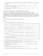
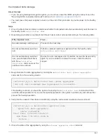
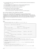
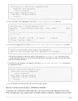


cluster_B::> metrocluster show
Cluster Configuration State Mode
-------------------- ------------------- ---------
Local: cluster_B configured switchover
Remote: cluster_A configured waiting-for-switchback
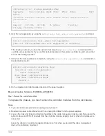
The switchback operation is complete when the clusters are in the
normal
state.:
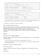
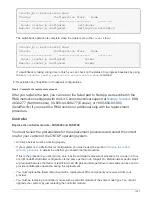
cluster_B::> metrocluster show
Cluster Configuration State Mode
-------------------- ------------------- ---------
Local: cluster_B configured normal
Remote: cluster_A configured normal
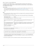
If a switchback is taking a long time to finish, you can check on the status of in-progress baselines by using
the
metrocluster config-replication resync-status show
command.
6. Reestablish any SnapMirror or SnapVault configurations.
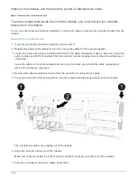
Step 4: Complete the replacement process
After you replace the part, you can return the failed part to NetApp, as described in the
RMA instructions shipped with the kit. Contact technical support at
, 888-
463-8277 (North America), 00-800-44-638277 (Europe), or +800-800-80-800
(Asia/Pacific) if you need the RMA number or additional help with the replacement
procedure.
Controller
Replace the controller module - FAS8300 and FAS8700
You must review the prerequisites for the replacement procedure and select the correct
one for your version of the ONTAP operating system.
• All drive shelves must be working properly.
• If your system is in a MetroCluster configuration, you must review the section
to determine whether you should use this procedure.
If this is the procedure you should use, note that the controller replacement procedure for a node in a four
or eight node MetroCluster configuration is the same as that in an HA pair. No MetroCluster-specific steps
are required because the failure is restricted to an HA pair and storage failover commands can be used to
provide nondisruptive operation during the replacement.
• You must replace the failed component with a replacement FRU component you received from your
provider.
• You must be replacing a controller module with a controller module of the same model type. You cannot
upgrade your system by just replacing the controller module.
1357
Summary of Contents for AFF A700
Page 4: ...AFF and FAS System Documentation 1...
Page 208: ...3 Close the controller module cover and tighten the thumbscrew 205...
Page 248: ...2 Close the controller module cover and tighten the thumbscrew 245...
Page 308: ...Power supply Cam handle release latch Power and Fault LEDs Cam handle 305...
Page 381: ...Power supply Cam handle release latch Power and Fault LEDs Cam handle 378...
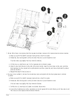
Page 437: ...1 Locate the DIMMs on your controller module 434...
Page 605: ...602...
Page 1117: ...3 Close the controller module cover and tighten the thumbscrew 1114...
Page 1157: ...2 Close the controller module cover and tighten the thumbscrew 1154...
Page 1228: ...Power supply Cam handle release latch Power and Fault LEDs Cam handle 1225...
Page 1300: ...Power supply Cam handle release latch Power and Fault LEDs Cam handle 1297...
Page 1462: ...Installing SuperRail to round hole four post rack 1459...
Page 1602: ...1599...
Page 1630: ...1627...
Page 1634: ...Orange ring on horizontal bracket Cable chain 1631...
Page 1645: ...Guide rail 1642...
Page 1669: ...Attention LED light on 1666...


