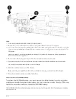

Steps
1. If you are not already grounded, properly ground yourself.
2. Release the power cable retainers, and then unplug the cables from the power supplies.
3. Loosen the hook and loop strap binding the cables to the cable management device, and then unplug the
system cables and SFPs (if needed) from the controller module, keeping track of where the cables were
connected.
Leave the cables in the cable management device so that when you reinstall the cable management
device, the cables are organized.
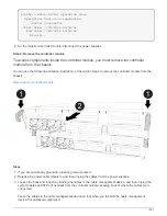
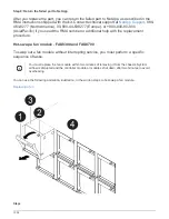
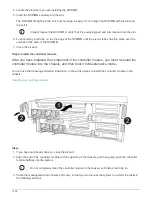
4. Remove the cable management device from the controller module and set it aside.
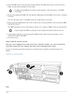
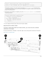
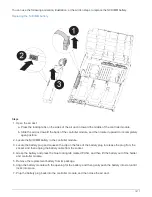
5. Press down on both of the locking latches, and then rotate both latches downward at the same time.
The controller module moves slightly out of the chassis.
6. Slide the controller module out of the chassis.
Make sure that you support the bottom of the controller module as you slide it out of the chassis.
7. Place the controller module on a stable, flat surface.
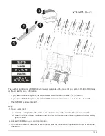
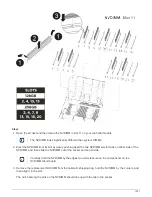
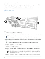
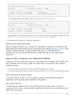
Step 3: Replace the NVDIMM
To replace the NVDIMM, you must locate it in the controller module using the FRU map
on top of the air duct or locate the Attention LED using the FRU Map on the top of the slot
1 riser.
• The NVDIMM LED blinks while destaging contents when you halt the system. After the destage is
complete, the LED turns off.
• Although the contents of the NVDIMM is encrypted, it is a best practice to erase the contents of the
NVDIMM before replacing it. For more information, see the
on the NetApp Support
Site.
You must log into the NetApp Support Site to display the
Statement of Volatility
for your
system.
You can use the following animation, illustration, or the written steps to replace the NVDIMM.
The animation and illustration show empty slots for sockets without DIMMs. These empty
sockets are populated with blanks.
1400
Summary of Contents for AFF A700
Page 4: ...AFF and FAS System Documentation 1...
Page 208: ...3 Close the controller module cover and tighten the thumbscrew 205...
Page 248: ...2 Close the controller module cover and tighten the thumbscrew 245...
Page 308: ...Power supply Cam handle release latch Power and Fault LEDs Cam handle 305...
Page 381: ...Power supply Cam handle release latch Power and Fault LEDs Cam handle 378...
Page 437: ...1 Locate the DIMMs on your controller module 434...
Page 605: ...602...
Page 1117: ...3 Close the controller module cover and tighten the thumbscrew 1114...
Page 1157: ...2 Close the controller module cover and tighten the thumbscrew 1154...
Page 1228: ...Power supply Cam handle release latch Power and Fault LEDs Cam handle 1225...
Page 1300: ...Power supply Cam handle release latch Power and Fault LEDs Cam handle 1297...
Page 1462: ...Installing SuperRail to round hole four post rack 1459...
Page 1602: ...1599...
Page 1630: ...1627...
Page 1634: ...Orange ring on horizontal bracket Cable chain 1631...
Page 1645: ...Guide rail 1642...
Page 1669: ...Attention LED light on 1666...


