
You will connect the rest of the cables to the controller module later in this procedure.
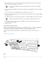
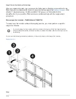
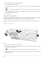
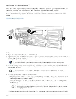
4. Complete the installation of the controller module:
a. Plug the power cord into the power supply, reinstall the power cable locking collar, and then connect
the power supply to the power source.
b. Using the locking latches, firmly push the controller module into the chassis until the locking latches
begin to rise.
Do not use excessive force when sliding the controller module into the chassis to avoid
damaging the connectors.
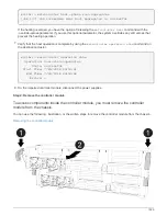
c. Fully seat the controller module in the chassis by rotating the locking latches upward, tilting them so
that they clear the locking pins, gently push the controller all the way in, and then lower the locking
latches into the locked position.
The controller module begins to boot as soon as it is fully seated in the chassis. Be prepared to
interrupt the boot process.
d. If you have not already done so, reinstall the cable management device.
e. Interrupt the normal boot process and boot to LOADER by pressing
Ctrl-C
.
If your system stops at the boot menu, select the option to boot to LOADER.
f. At the LOADER prompt, enter
bye
to reinitialize the PCIe cards and other components.
g. Interrupt the boot process and boot to the LOADER prompt by pressing
Ctrl-C
.
If your system stops at the boot menu, select the option to boot to LOADER.
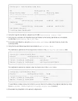
Step 5: Run diagnostics
After you have replaced the NVDIMM in your system, you should run diagnostic tests on
that component.
Your system must be at the LOADER prompt to start diagnostics.
All commands in the diagnostic procedures are issued from the node where the component is being replaced.
Steps
1. If the node to be serviced is not at the LOADER prompt, reboot the node:
system node halt -node
node_name
After you issue the command, you should wait until the system stops at the LOADER prompt.
2. At the LOADER prompt, access the special drivers specifically designed for system-level diagnostics to
function properly:
boot_diags
3. Select
Scan System
from the displayed menu to enable running the diagnostics tests.
4. Select
Test Memory
from the displayed menu.
5. Select
NVDIMM Test
from the displayed menu.
1403
Summary of Contents for AFF A700
Page 4: ...AFF and FAS System Documentation 1...
Page 208: ...3 Close the controller module cover and tighten the thumbscrew 205...
Page 248: ...2 Close the controller module cover and tighten the thumbscrew 245...
Page 308: ...Power supply Cam handle release latch Power and Fault LEDs Cam handle 305...
Page 381: ...Power supply Cam handle release latch Power and Fault LEDs Cam handle 378...
Page 437: ...1 Locate the DIMMs on your controller module 434...
Page 605: ...602...
Page 1117: ...3 Close the controller module cover and tighten the thumbscrew 1114...
Page 1157: ...2 Close the controller module cover and tighten the thumbscrew 1154...
Page 1228: ...Power supply Cam handle release latch Power and Fault LEDs Cam handle 1225...
Page 1300: ...Power supply Cam handle release latch Power and Fault LEDs Cam handle 1297...
Page 1462: ...Installing SuperRail to round hole four post rack 1459...
Page 1602: ...1599...
Page 1630: ...1627...
Page 1634: ...Orange ring on horizontal bracket Cable chain 1631...
Page 1645: ...Guide rail 1642...
Page 1669: ...Attention LED light on 1666...


