7. Position the battery pack by aligning the battery holder key ribs to the “V” notches on the sheet metal side
wall.
8. Slide the battery pack down along the sheet metal side wall until the support tabs on the side wall hook into
the slots on the battery pack, and the battery pack latch engages and clicks into the opening on the side
wall.
Step 3: Move the boot media
You must locate the boot media and follow the directions to remove it from the old
controller module and insert it in the new controller module.
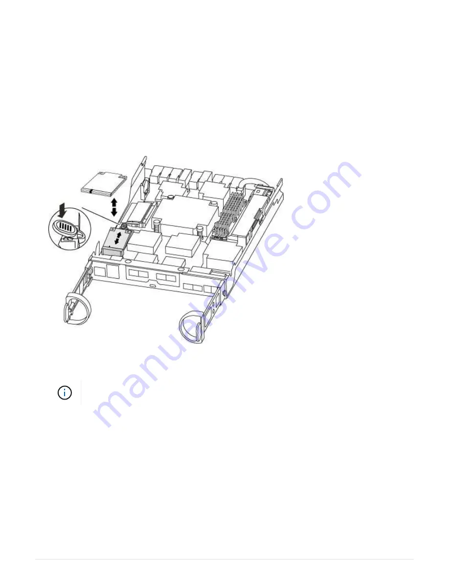
1. Locate the boot media using the following illustration or the FRU map on the controller module:
2. Press the blue button on the boot media housing to release the boot media from its housing, and then
gently pull it straight out of the boot media socket.
Do not twist or pull the boot media straight up, because this could damage the socket or the
boot media.
3. Move the boot media to the new controller module, align the edges of the boot media with the socket
housing, and then gently push it into the socket.
4. Check the boot media to make sure that it is seated squarely and completely in the socket.
If necessary, remove the boot media and reseat it into the socket.
5. Push the boot media down to engage the locking button on the boot media housing.
Step 4: Move the DIMMs
To move the DIMMs, you must follow the directions to locate and move them from the old
controller module into the replacement controller module.
139
Summary of Contents for AFF A700
Page 4: ...AFF and FAS System Documentation 1...
Page 208: ...3 Close the controller module cover and tighten the thumbscrew 205...
Page 248: ...2 Close the controller module cover and tighten the thumbscrew 245...
Page 308: ...Power supply Cam handle release latch Power and Fault LEDs Cam handle 305...
Page 381: ...Power supply Cam handle release latch Power and Fault LEDs Cam handle 378...
Page 437: ...1 Locate the DIMMs on your controller module 434...
Page 605: ...602...
Page 1117: ...3 Close the controller module cover and tighten the thumbscrew 1114...
Page 1157: ...2 Close the controller module cover and tighten the thumbscrew 1154...
Page 1228: ...Power supply Cam handle release latch Power and Fault LEDs Cam handle 1225...
Page 1300: ...Power supply Cam handle release latch Power and Fault LEDs Cam handle 1297...
Page 1462: ...Installing SuperRail to round hole four post rack 1459...
Page 1602: ...1599...
Page 1630: ...1627...
Page 1634: ...Orange ring on horizontal bracket Cable chain 1631...
Page 1645: ...Guide rail 1642...
Page 1669: ...Attention LED light on 1666...