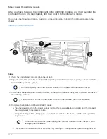
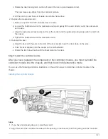

Step 7: Restore the controller module to operation after running diagnostics
After completing diagnostics, you must recable the system, give back the controller
module, and then reenable automatic giveback.
Steps
1. Recable the system, as needed.
If you removed the media converters (QSFPs or SFPs), remember to reinstall them if you are using fiber
optic cables.
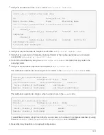
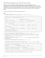
2. Return the node to normal operation by giving back its storage:
storage failover giveback
-ofnode
impaired_node_name
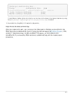
3. If automatic giveback was disabled, reenable it:
storage failover modify -node local -auto
-giveback true
Step 8: Return the failed part to NetApp
After you replace the part, you can return the failed part to NetApp, as described in the
RMA instructions shipped with the kit. Contact technical support at
, 888-
463-8277 (North America), 00-800-44-638277 (Europe), or +800-800-80-800
(Asia/Pacific) if you need the RMA number or additional help with the replacement
procedure.
Replace a power supply - FAS8300 and FAS8700
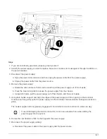
Replacing a power supply (PSU) involves disconnecting the target PSU from the power
source, unplugging the power cable, removing the old PSU and installing the replacement
PSU, and then reconnecting the replacement PSU to the power source.
• The power supplies are redundant and hot-swappable.
• This procedure is written for replacing one power supply at a time.
It is a best practice to replace the power supply within two minutes of removing it from the
chassis. The system continues to function, but ONTAP sends messages to the console
about the degraded power supply until the power supply is replaced.
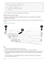
You can use the following animation, illustration, or the written steps to replace the power supply.
1426
Summary of Contents for AFF A700
Page 4: ...AFF and FAS System Documentation 1...
Page 208: ...3 Close the controller module cover and tighten the thumbscrew 205...
Page 248: ...2 Close the controller module cover and tighten the thumbscrew 245...
Page 308: ...Power supply Cam handle release latch Power and Fault LEDs Cam handle 305...
Page 381: ...Power supply Cam handle release latch Power and Fault LEDs Cam handle 378...
Page 437: ...1 Locate the DIMMs on your controller module 434...
Page 605: ...602...
Page 1117: ...3 Close the controller module cover and tighten the thumbscrew 1114...
Page 1157: ...2 Close the controller module cover and tighten the thumbscrew 1154...
Page 1228: ...Power supply Cam handle release latch Power and Fault LEDs Cam handle 1225...
Page 1300: ...Power supply Cam handle release latch Power and Fault LEDs Cam handle 1297...
Page 1462: ...Installing SuperRail to round hole four post rack 1459...
Page 1602: ...1599...
Page 1630: ...1627...
Page 1634: ...Orange ring on horizontal bracket Cable chain 1631...
Page 1645: ...Guide rail 1642...
Page 1669: ...Attention LED light on 1666...


