
Steps
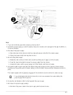
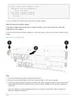
1. If you have not already done so, close the air duct or controller module cover.
2. Align the end of the controller module with the opening in the chassis, and then gently push the controller
module halfway into the system.
Do not completely insert the controller module in the chassis until instructed to do so.
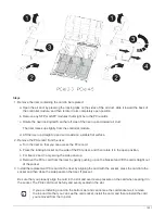
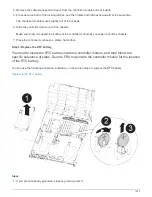
3. Recable the system, as needed.
If you removed the media converters (QSFPs or SFPs), remember to reinstall them if you are using fiber
optic cables.
4. If the power supplies were unplugged, plug them back in and reinstall the power cable retainers.
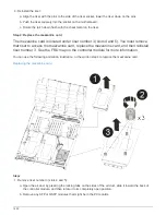
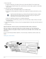
5. Complete the installation of the controller module:
a. Using the locking latches, firmly push the controller module into the chassis until it meets the midplane
and is fully seated.
The locking latches rise when the controller module is fully seated.
Do not use excessive force when sliding the controller module into the chassis to avoid
damaging the connectors.
The controller module begins to boot as soon as it is fully seated in the chassis. Be prepared to
interrupt the boot process.
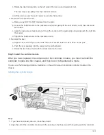
b. Fully seat the controller module in the chassis by rotating the locking latches upward, tilting them so
that they clear the locking pins, gently push the controller all the way in, and then lower the locking
latches into the locked position.
c. If you have not already done so, reinstall the cable management device.
d. Interrupt the normal boot process and boot to LOADER by pressing
Ctrl-C
.
If your system stops at the boot menu, select the option to boot to LOADER.
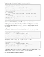
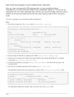
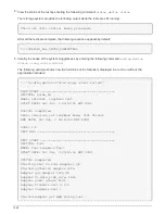
6. Reset the time and date on the controller:
a. Check the date and time on the healthy node with the
show date
command.
b. At the LOADER prompt on the target node, check the time and date.
c. If necessary, modify the date with the
set date mm/dd/yyyy
command.
d. If necessary, set the time, in GMT, using the
set time hh:mm:ss
command.
e. Confirm the date and time on the target node.
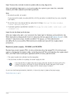
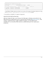
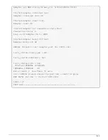
7. At the LOADER prompt, enter
bye
to reinitialize the PCIe cards and other components and let the node
reboot.
8. Return the node to normal operation by giving back its storage:
storage failover giveback
-ofnode
impaired_node_name
9. If automatic giveback was disabled, reenable it:
storage failover modify -node local -auto
-giveback true
1435
Summary of Contents for AFF A700
Page 4: ...AFF and FAS System Documentation 1...
Page 208: ...3 Close the controller module cover and tighten the thumbscrew 205...
Page 248: ...2 Close the controller module cover and tighten the thumbscrew 245...
Page 308: ...Power supply Cam handle release latch Power and Fault LEDs Cam handle 305...
Page 381: ...Power supply Cam handle release latch Power and Fault LEDs Cam handle 378...
Page 437: ...1 Locate the DIMMs on your controller module 434...
Page 605: ...602...
Page 1117: ...3 Close the controller module cover and tighten the thumbscrew 1114...
Page 1157: ...2 Close the controller module cover and tighten the thumbscrew 1154...
Page 1228: ...Power supply Cam handle release latch Power and Fault LEDs Cam handle 1225...
Page 1300: ...Power supply Cam handle release latch Power and Fault LEDs Cam handle 1297...
Page 1462: ...Installing SuperRail to round hole four post rack 1459...
Page 1602: ...1599...
Page 1630: ...1627...
Page 1634: ...Orange ring on horizontal bracket Cable chain 1631...
Page 1645: ...Guide rail 1642...
Page 1669: ...Attention LED light on 1666...