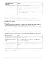
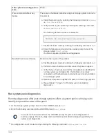
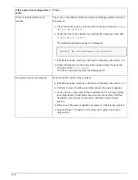
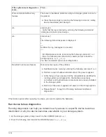
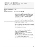

If the system-level diagnostics
tests…
Then…
Were completed without any
failures
There are no hardware problems and your storage system returns to
the prompt.
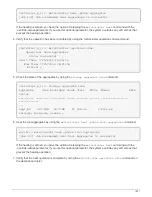
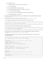
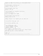
a. Clear the status logs by entering the following command:
sldiag
device clearstatus
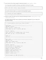
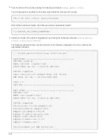
b. Verify that the log is cleared by entering the following command:
sldiag device status
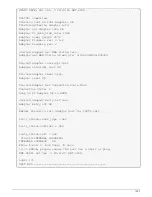
The following default response is displayed:
SLDIAG: No log messages are present.
c. Exit Maintenance mode by entering the following command:
halt
d. Enter the following command at the Loader prompt to boot the
storage system:
boot_ontap
You have completed system-level diagnostics.
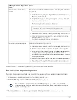
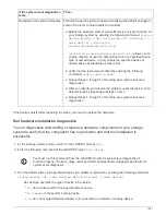
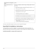
Resulted in some test failures
Determine the cause of the problem.
a. Exit Maintenance mode by entering the following command:
halt
b. Perform a clean shutdown and disconnect the power supplies.
c. Verify that you have observed all the considerations identified for
running system-level diagnostics, that cables are securely
connected, and that hardware components are properly installed
in the storage system.
d. Reconnect the power supplies and power on the storage system.
e. Repeat Steps 1 through 7 of
Running system installation
diagnostics
.
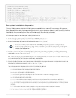
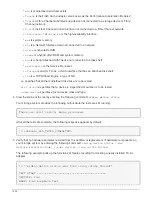
Run system panic diagnostics
Running diagnostics after your storage system suffers a system panic can help you to
identify the possible cause of the panic.
1. At the storage system prompt, switch to the LOADER prompt:
halt
2. Enter the following command at the LOADER prompt:
boot_diags
You must run this command from the LOADER prompt for system-level diagnostics to
function properly. The boot_diags command starts special drivers designed specifically for
system-level diagnostics.
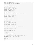
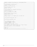
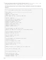
3. Run diagnostics on all the devices by entering the following command:
sldiag device run
1444
Summary of Contents for AFF A700
Page 4: ...AFF and FAS System Documentation 1...
Page 208: ...3 Close the controller module cover and tighten the thumbscrew 205...
Page 248: ...2 Close the controller module cover and tighten the thumbscrew 245...
Page 308: ...Power supply Cam handle release latch Power and Fault LEDs Cam handle 305...
Page 381: ...Power supply Cam handle release latch Power and Fault LEDs Cam handle 378...
Page 437: ...1 Locate the DIMMs on your controller module 434...
Page 605: ...602...
Page 1117: ...3 Close the controller module cover and tighten the thumbscrew 1114...
Page 1157: ...2 Close the controller module cover and tighten the thumbscrew 1154...
Page 1228: ...Power supply Cam handle release latch Power and Fault LEDs Cam handle 1225...
Page 1300: ...Power supply Cam handle release latch Power and Fault LEDs Cam handle 1297...
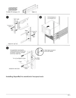
Page 1462: ...Installing SuperRail to round hole four post rack 1459...
Page 1602: ...1599...
Page 1630: ...1627...
Page 1634: ...Orange ring on horizontal bracket Cable chain 1631...
Page 1645: ...Guide rail 1642...
Page 1669: ...Attention LED light on 1666...