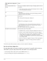
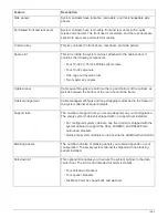
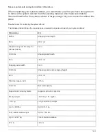

Feature
Description
Side panels
System cabinets have lockable, removable, and interchangeable side
panels.
Perforated front and rear doors
System cabinets have removable front and rear doors with a quick
release mechanism. The front door is reversible, and the rear doors are
split. Both doors are perforated for cooling.
Common key
This key unlocks the front doors, rear doors, and side panels.
Spares kit
This kit is inside the system cabinet, attached to the cabinet door. It
contains the following components:
• Four 10-32 x 0.75 inch Phillips pilot screws
• Four 10-32 cage nuts
• One cage nut insertion tool
• Two master key copies
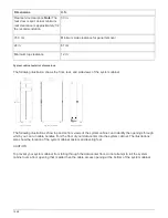
Cable access
Cable pass-throughs are built into the top and bottom of the cabinet, as
well as between the bottom of the rear door and the frame.
Cable management
Cable management hook and loop strapping is attached to the frame of
the system cabinet at equal intervals.
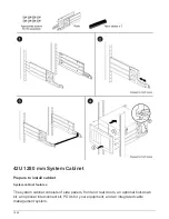
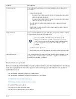
Support rails
The number of support rails you receive depends on your configuration.
The empty system cabinet is shipped with no support rails installed.
• For configured system cabinets, one fixed rail kit is shipped with the
system cabinet to support the 80xx, FAS8200, and DS4486 rear
hold-down brackets.
• Quick-ship system cabinets do not include the additional fixed rail kit.
Blanking panels
The number and size of blanking panels you receive depends on your
configuration. The empty system cabinet is shipped with no blanking
panels installed.
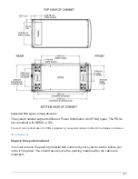
Bolt-down kit
This optional kit enables you to secure the system cabinet to the data
center floor. The kit it is not intended for seismic stability.
• Four bolt-down brackets
• Four spacer brackets
• Six M8x20 mm hex head bolts and washers
1463
Summary of Contents for AFF A700
Page 4: ...AFF and FAS System Documentation 1...
Page 208: ...3 Close the controller module cover and tighten the thumbscrew 205...
Page 248: ...2 Close the controller module cover and tighten the thumbscrew 245...
Page 308: ...Power supply Cam handle release latch Power and Fault LEDs Cam handle 305...
Page 381: ...Power supply Cam handle release latch Power and Fault LEDs Cam handle 378...
Page 437: ...1 Locate the DIMMs on your controller module 434...
Page 605: ...602...
Page 1117: ...3 Close the controller module cover and tighten the thumbscrew 1114...
Page 1157: ...2 Close the controller module cover and tighten the thumbscrew 1154...
Page 1228: ...Power supply Cam handle release latch Power and Fault LEDs Cam handle 1225...
Page 1300: ...Power supply Cam handle release latch Power and Fault LEDs Cam handle 1297...
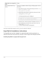
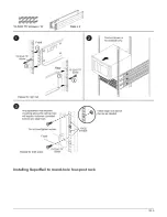
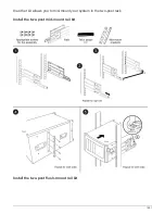
Page 1462: ...Installing SuperRail to round hole four post rack 1459...
Page 1602: ...1599...
Page 1630: ...1627...
Page 1634: ...Orange ring on horizontal bracket Cable chain 1631...
Page 1645: ...Guide rail 1642...
Page 1669: ...Attention LED light on 1666...


