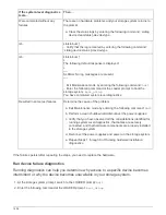
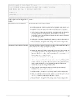
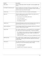
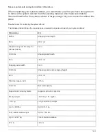
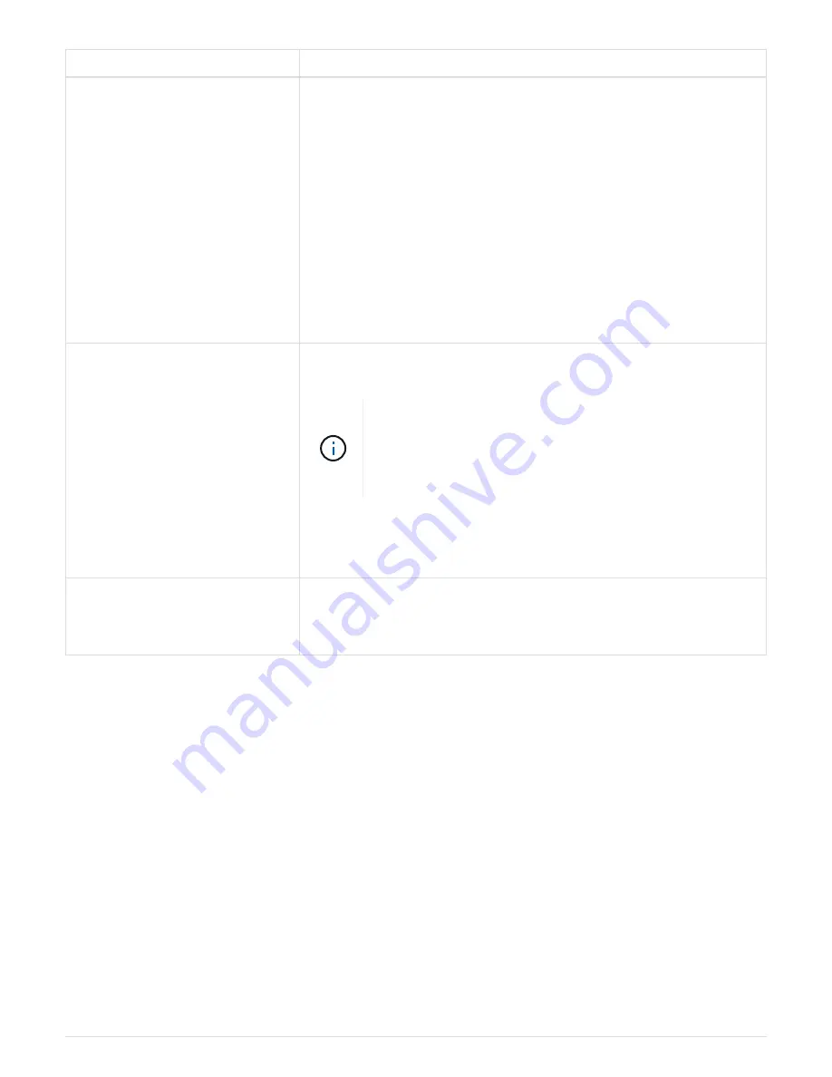
Feature
Description
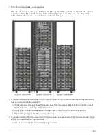
Interconnect kit
This optional kit enables you to connect multiple system cabinets to
each other.
• Interconnect brackets
◦
One set of four interconnect brackets for connecting the system
cabinets with side panels on
◦
One set of four interconnect brackets for connecting the system
cabinets with the side panels off
• Four M12x20 Torx-30 screws used in system cabinet with side
panels on.
• Eight M6x10 countersunk Torx-30 screws used in system cabinet
with side panels off.
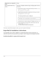
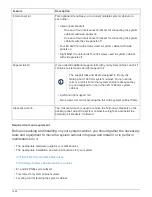
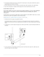
Support rail kit
If you ordered additional support rails with your system cabinet, each kit
contains one left and one right support rail.
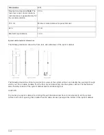
The support rails and kit are designed to fit only the
NetApp 42U 1280 mm system cabinet. Do not use the
rails or a rail kit from other system cabinets because they
are not designed for use in the 42U 1280 mm system
cabinet.
• A left and right support rail
• Two screws per rail for securing the rail to the system cabinet frame
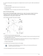
Crescent wrench
The crescent wrench is used to remove the hold-down brackets on the
packing pallet, adjust the system cabinet leveling feet, and install the
bolt-down kit brackets, if ordered.
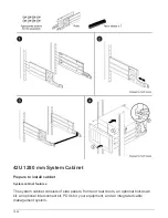
Required tools and equipment
Before unpacking and installing on your system cabinet, you should gather the necessary
tools and equipment to move the system cabinet into place and install it or to perform
maintenance on it.
• The appropriate hardware guide for your disk shelves
• The appropriate installation and setup instructions for your system
All Flash FAS Documentation Resources
FAS Storage Systems documentation resources
• #1 and #2 Phillips screwdrivers
• Torx driver for system cabinet screws
• Leveling tool for leveling the system cabinet
1464
Summary of Contents for AFF A700
Page 4: ...AFF and FAS System Documentation 1...
Page 208: ...3 Close the controller module cover and tighten the thumbscrew 205...
Page 248: ...2 Close the controller module cover and tighten the thumbscrew 245...
Page 308: ...Power supply Cam handle release latch Power and Fault LEDs Cam handle 305...
Page 381: ...Power supply Cam handle release latch Power and Fault LEDs Cam handle 378...
Page 437: ...1 Locate the DIMMs on your controller module 434...
Page 605: ...602...
Page 1117: ...3 Close the controller module cover and tighten the thumbscrew 1114...
Page 1157: ...2 Close the controller module cover and tighten the thumbscrew 1154...
Page 1228: ...Power supply Cam handle release latch Power and Fault LEDs Cam handle 1225...
Page 1300: ...Power supply Cam handle release latch Power and Fault LEDs Cam handle 1297...
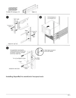
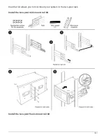
Page 1462: ...Installing SuperRail to round hole four post rack 1459...
Page 1602: ...1599...
Page 1630: ...1627...
Page 1634: ...Orange ring on horizontal bracket Cable chain 1631...
Page 1645: ...Guide rail 1642...
Page 1669: ...Attention LED light on 1666...