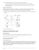


Remove the system cabinet door
You must remove the system cabinet door and side panels to move the illuminated badge
and components, and to reverse the door.
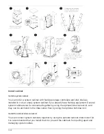
1. Open the system cabinet door if it is not already open.
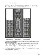
2. Perform the appropriate action depending on whether your cabinets are connected with the interconnect
kit.
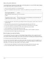
If your system cabinet is…
Then…
Not connected to another system
cabinet
Go to the next step.
Connected to another system
cabinet with an interconnect kit
Remove all four interconnect kit brackets and set the brackets and
screws in a safe place.
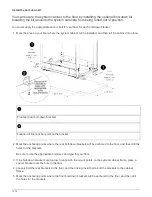
3. Unlock both side panels, disconnect the grounding wires from the side panels, and then remove them and
set them aside.
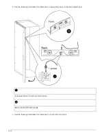
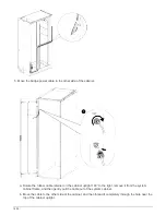
4. Disconnect the grounding wire from the grounding spade located at the top of the door.
5. Unscrew the grounding lug and wire assembly from the system cabinet frame and set it aside.
6. Unscrew the grounding lug assembly from the system cabinet door and set it aside.
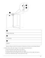
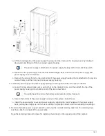
7. Lift the top hinge pin until it clears the bottom of the hinge.
8. Gently tip the top of the door away from the system cabinet frame, and then release the hinge pin.
9. Lift the door off the bottom hinge, and set the door aside.
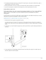
Move the badge power supply and cabling
You must move the power supply and illuminated badge cabling to the opposite side of
the system cabinet frame before you reverse the door and reinstall the illuminated badge.
You must have removed the system cabinet door and side panels.
You must move the illuminated badge power supply, power cable, and cabling conduit to the opposite side of
the system cabinet when you reverse the system cabinet door. The assembly is designed so that the cable to
the badge is on the side of the cabinet where the door hinge is installed.
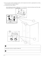
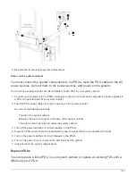
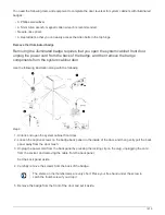
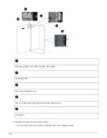
1. Open the power cable retaining clip, and then disconnect the power cable from the power supply.
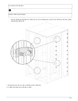
2. Remove the power supply housing and power supply, using the illustration for reference:
1480
Summary of Contents for AFF A700
Page 4: ...AFF and FAS System Documentation 1...
Page 208: ...3 Close the controller module cover and tighten the thumbscrew 205...
Page 248: ...2 Close the controller module cover and tighten the thumbscrew 245...
Page 308: ...Power supply Cam handle release latch Power and Fault LEDs Cam handle 305...
Page 381: ...Power supply Cam handle release latch Power and Fault LEDs Cam handle 378...
Page 437: ...1 Locate the DIMMs on your controller module 434...
Page 605: ...602...
Page 1117: ...3 Close the controller module cover and tighten the thumbscrew 1114...
Page 1157: ...2 Close the controller module cover and tighten the thumbscrew 1154...
Page 1228: ...Power supply Cam handle release latch Power and Fault LEDs Cam handle 1225...
Page 1300: ...Power supply Cam handle release latch Power and Fault LEDs Cam handle 1297...
Page 1462: ...Installing SuperRail to round hole four post rack 1459...
Page 1602: ...1599...
Page 1630: ...1627...
Page 1634: ...Orange ring on horizontal bracket Cable chain 1631...
Page 1645: ...Guide rail 1642...
Page 1669: ...Attention LED light on 1666...