


If automatic drive assignment is enabled, the output shows
on
in the
Auto Assign
column (for each
controller module).
2. If automatic drive assignment is enabled, disable it:
storage disk option modify -node
node_name -autoassign off
You must disable automatic drive assignment on both controller modules.
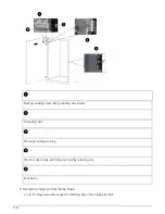
Install a drive shelf for a hot-add
Installing a new NS224 drive shelf involves installing the shelf into a rack or cabinet,
connecting the power cords (which automatically powers on the shelf), and then setting
the shelf ID.
Before you begin
• You must have met the system requirements.
• You must have completed the applicable preparation procedures.
Steps
1. Install the rail mount kit that came with your shelf by using the installation flyer that came in the kit box.
Do not flange-mount the shelf.
2. Install and secure the shelf onto the support brackets and rack or cabinet by using the installation flyer.
A fully loaded NS224 shelf can weigh up to 66.78 lbs (30.29 kg) and requires two people to
lift or use of a hydraulic lift. Avoid removing shelf components (from the front or rear of the
shelf) to reduce the shelf weight, because shelf weight will become unbalanced.
3. Connect the power cords to the shelf, secure them in with the power cord retainer, and then connect the
power cords to different power sources for resiliency.
A shelf powers up when connected to a power source; it does not have power switches. When functioning
correctly, a power supply’s bicolored LED illuminates green.
4. Set the shelf ID to a number that is unique within the HA pair:
More detailed instructions are available:
Change a shelf ID - NS224 shelves
a. Remove the left end cap and locate the small hole to the right of the LEDs.
b. Insert the end of a paper clip or similar tool into the small hole to reach the shelf ID button.
c. Press and hold the button (for up to 15 seconds) until the first number on the digital display blinks, and
then release the button.
1498
Summary of Contents for AFF A700
Page 4: ...AFF and FAS System Documentation 1...
Page 208: ...3 Close the controller module cover and tighten the thumbscrew 205...
Page 248: ...2 Close the controller module cover and tighten the thumbscrew 245...
Page 308: ...Power supply Cam handle release latch Power and Fault LEDs Cam handle 305...
Page 381: ...Power supply Cam handle release latch Power and Fault LEDs Cam handle 378...
Page 437: ...1 Locate the DIMMs on your controller module 434...
Page 605: ...602...
Page 1117: ...3 Close the controller module cover and tighten the thumbscrew 1114...
Page 1157: ...2 Close the controller module cover and tighten the thumbscrew 1154...
Page 1228: ...Power supply Cam handle release latch Power and Fault LEDs Cam handle 1225...
Page 1300: ...Power supply Cam handle release latch Power and Fault LEDs Cam handle 1297...
Page 1462: ...Installing SuperRail to round hole four post rack 1459...
Page 1602: ...1599...
Page 1630: ...1627...
Page 1634: ...Orange ring on horizontal bracket Cable chain 1631...
Page 1645: ...Guide rail 1642...
Page 1669: ...Attention LED light on 1666...


