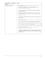
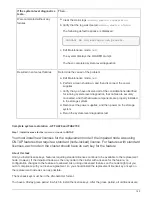
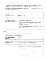
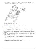
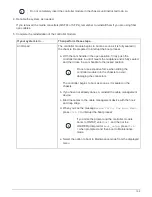
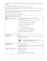

If the system-level diagnostics
tests…
Then…
Were completed without any
failures
a. Clear the status logs:
sldiag device clearstatus
b. Verify that the log was cleared:
sldiag device status
The following default response is displayed:
SLDIAG: No log messages are present.
c. Exit Maintenance mode:
halt
The system displays the LOADER prompt.
You have completed system-level diagnostics.
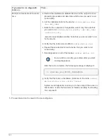
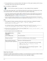
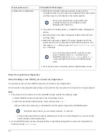
Resulted in some test failures
Determine the cause of the problem.
a. Exit Maintenance mode:
halt
b. Perform a clean shutdown, and then disconnect the power
supplies.
c. Verify that you have observed all of the considerations identified
for running system-level diagnostics, that cables are securely
connected, and that hardware components are properly installed
in the storage system.
d. Reconnect the power supplies, and then power on the storage
system.
e. Rerun the system-level diagnostics test.
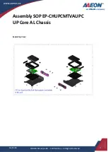
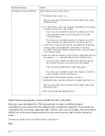
Complete system restoration - AFF A220 and FAS2700
Step 1: Install licenses for the
replacement
node in ONTAP
You must install new licenses for the
replacement
node if the impaired node was using
ONTAP features that require a standard (node-locked) license. For features with standard
licenses, each node in the cluster should have its own key for the feature.
About this task
Until you install license keys, features requiring standard licenses continue to be available to the
replacement
node. However, if the impaired node was the only node in the cluster with a license for the feature, no
configuration changes to the feature are allowed. Also, using unlicensed features on the node might put you
out of compliance with your license agreement, so you should install the replacement license key or keys on
the
replacement
node as soon as possible.
The licenses keys must be in the 28-character format.
You have a 90-day grace period in which to install the license keys. After the grace period, all old licenses are
149
Summary of Contents for AFF A700
Page 4: ...AFF and FAS System Documentation 1...
Page 208: ...3 Close the controller module cover and tighten the thumbscrew 205...
Page 248: ...2 Close the controller module cover and tighten the thumbscrew 245...
Page 308: ...Power supply Cam handle release latch Power and Fault LEDs Cam handle 305...
Page 381: ...Power supply Cam handle release latch Power and Fault LEDs Cam handle 378...
Page 437: ...1 Locate the DIMMs on your controller module 434...
Page 605: ...602...
Page 1117: ...3 Close the controller module cover and tighten the thumbscrew 1114...
Page 1157: ...2 Close the controller module cover and tighten the thumbscrew 1154...
Page 1228: ...Power supply Cam handle release latch Power and Fault LEDs Cam handle 1225...
Page 1300: ...Power supply Cam handle release latch Power and Fault LEDs Cam handle 1297...
Page 1462: ...Installing SuperRail to round hole four post rack 1459...
Page 1602: ...1599...
Page 1630: ...1627...
Page 1634: ...Orange ring on horizontal bracket Cable chain 1631...
Page 1645: ...Guide rail 1642...
Page 1669: ...Attention LED light on 1666...