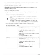

• Drive firmware is automatically updated (nondisruptively) on new drives that have non current firmware
versions.
Drive firmware checks occur every two minutes.
• If needed, you can turn on the shelf’s location (blue) LEDs to aid in physically locating the affected shelf:
storage shelf location-led modify -shelf-name
shelf_name
-led-status on
If you do not know the
shelf_name
of the affected shelf, run the
storage shelf show
command.
A shelf has three location LEDs: one on the operator display panel and one on each NSM module.
Location LEDs remain illuminated for 30 minutes. You can turn them off by entering the same command,
but using the
off
option.
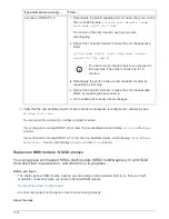
• When you unpack the replacement drive, save all packing materials for use when you return the failed
drive.
If you need the RMA number or additional help with the replacement procedure, contact technical support
at
, 888-463-8277 (North America), 00-800-44-638277 (Europe), or +800-800-80-800
(Asia/Pacific).
• The following video provides an overview of the physical removal and insertion portions of the drive hot-
swap procedure.
Hot-swapping a drive in an NS224 drive shelf
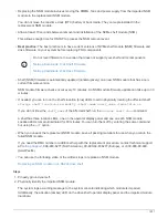
Steps
1. If you want to manually assign drive ownership for the replacement drive, you need to disable automatic
drive assignment if it is enabled.
You need to manually assign drive ownership if drives in the shelf are owned by both
controller modules in the HA pair.
You manually assign drive ownership and then reenable automatic drive assignment later in
this procedure.
a. Verify whether automatic drive assignment is enabled:
storage disk option show
You can enter the command on either controller module.
If automatic drive assignment is enabled, the output shows
on
in the
Auto Assign
column (for each
controller module).
b. If automatic drive assignment is enabled, disable it:
storage disk option modify -node
node_name -autoassign off
You must disable automatic drive assignment on both controller modules.
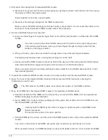
2. Properly ground yourself.
3. Physically identify the failed drive.
When a drive fails, the system logs a warning message to the system console indicating which drive failed.
1522
Summary of Contents for AFF A700
Page 4: ...AFF and FAS System Documentation 1...
Page 208: ...3 Close the controller module cover and tighten the thumbscrew 205...
Page 248: ...2 Close the controller module cover and tighten the thumbscrew 245...
Page 308: ...Power supply Cam handle release latch Power and Fault LEDs Cam handle 305...
Page 381: ...Power supply Cam handle release latch Power and Fault LEDs Cam handle 378...
Page 437: ...1 Locate the DIMMs on your controller module 434...
Page 605: ...602...
Page 1117: ...3 Close the controller module cover and tighten the thumbscrew 1114...
Page 1157: ...2 Close the controller module cover and tighten the thumbscrew 1154...
Page 1228: ...Power supply Cam handle release latch Power and Fault LEDs Cam handle 1225...
Page 1300: ...Power supply Cam handle release latch Power and Fault LEDs Cam handle 1297...
Page 1462: ...Installing SuperRail to round hole four post rack 1459...
Page 1602: ...1599...
Page 1630: ...1627...
Page 1634: ...Orange ring on horizontal bracket Cable chain 1631...
Page 1645: ...Guide rail 1642...
Page 1669: ...Attention LED light on 1666...