


Drives with no aggregates have a dash in the
Container Name
column.
c. Check the output to verify that ownership is removed from the drives.
Drives with no ownership have a dash in the
Owner
column.
If you have failed drives, they display broken in the
Container Type
column. (Failed
drives do not have ownership.)
The following output shows drives on the shelf being removed (shelf 2) are in a correct state for
removing the shelf. The aggregates are removed on all of the drives; therefore, a dash appears in the
Container Name
column for each drive. Ownership is also removed on all of the drives; therefore, a
dash appears in the
Owner
column for each drive.
cluster1::> storage disk show -shelf 2
Usable Disk Container Container
Disk Size Shelf Bay Type Type Name Owner
-------- -------- ----- --- ------ ----------- ---------- ---------
...
2.2.4 - 2 4 SSD-NVM spare - -
2.2.5 - 2 5 SSD-NVM spare - -
2.2.6 - 2 6 SSD-NVM broken - -
2.2.7 - 2 7 SSD-NVM spare - -
...
3. Physically locate the shelf you are removing.
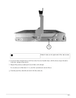
4. Disconnect the cabling from the shelf you are removing:
a. Disconnect the power cord from the power supply by opening the power cord retainer, and then unplug
the power cord from the power supply.
Power supplies do not have a power switch.
b. Disconnect the storage cabling (from the shelf to the controllers).
5. Physically remove the shelf from the rack or cabinet.
A fully loaded NS224 shelf can weigh up to 66.78 lbs (30.29 kg) and requires two people to
lift or use of a hydraulic lift. Avoid removing shelf components (from the front or rear of the
shelf) to reduce the shelf weight, because shelf weight will become unbalanced.
If your system was shipped in a cabinet, you must first unscrew the two Phillips screws
securing the shelf to the rear uprights. The screws are located on the inside shelf walls of
the bottom NSM module. You should remove both NSM modules to access the screws.
6. If you are removing more than one shelf, repeat steps 2 through 5.
Otherwise, go to the next step.
1528
Summary of Contents for AFF A700
Page 4: ...AFF and FAS System Documentation 1...
Page 208: ...3 Close the controller module cover and tighten the thumbscrew 205...
Page 248: ...2 Close the controller module cover and tighten the thumbscrew 245...
Page 308: ...Power supply Cam handle release latch Power and Fault LEDs Cam handle 305...
Page 381: ...Power supply Cam handle release latch Power and Fault LEDs Cam handle 378...
Page 437: ...1 Locate the DIMMs on your controller module 434...
Page 605: ...602...
Page 1117: ...3 Close the controller module cover and tighten the thumbscrew 1114...
Page 1157: ...2 Close the controller module cover and tighten the thumbscrew 1154...
Page 1228: ...Power supply Cam handle release latch Power and Fault LEDs Cam handle 1225...
Page 1300: ...Power supply Cam handle release latch Power and Fault LEDs Cam handle 1297...
Page 1462: ...Installing SuperRail to round hole four post rack 1459...
Page 1602: ...1599...
Page 1630: ...1627...
Page 1634: ...Orange ring on horizontal bracket Cable chain 1631...
Page 1645: ...Guide rail 1642...
Page 1669: ...Attention LED light on 1666...


