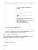
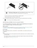

• Replacing the NSM module involves moving the DIMMs, fans and power supply from the impaired NSM
module to the replacement NSM module.
You do not move the real-time clock (RTC) battery or boot media. They come preinstalled in the
replacement NSM module.
• Allow at least 70 seconds between removal and installation of the NVMe shelf module (NSM).
This allows enough time for ONTAP to process the NSM removal event.
•
Best practice:
The best practice is to have current versions of NVMe shelf module (NSM) firmware and
drive firmware on your system before replacing FRU components.
Do not revert firmware to a version that does not support your shelf and its components.
NetApp Downloads: Disk Shelf Firmware
NetApp Downloads: Disk Drive Firmware
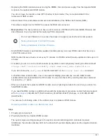
• Shelf (NSM) firmware is automatically updated (nondisruptively) on a new NSM module that has a non-
current firmware version.
NSM module firmware checks occur every 10 minutes. An NSM module firmware update can take up to 30
minutes.
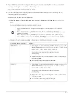
• If needed, you can turn on the shelf’s location (blue) LEDs to aid in physically locating the affected shelf:
storage shelf location-led modify -shelf-name
shelf_name
-led-status on
If you do not know the
shelf_name
of the affected shelf, run the
storage shelf show
command.
A shelf has three location LEDs: one on the operator display panel and one on each NSM module.
Location LEDs remain illuminated for 30 minutes. You can turn them off by entering the same command,
but using the
off
option.
• When you unpack the replacement NSM module, save all packing materials for use when you return the
failed NSM module.
If you need the RMA number or additional help with the replacement procedure, contact technical support
at
, 888-463-8277 (North America), 00-800-44-638277 (Europe), or +800-800-80-800
(Asia/Pacific).
• You can use the following video or the written steps to replace an NSM module.
Replacing an NSM module in an NS224 drive shelf
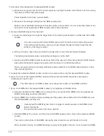
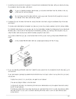
Steps
1. Properly ground yourself.
2. Physically identify the impaired NSM module.
The system logs a warning message to the system console indicating which module is impaired.
Additionally, the attention (amber) LED on the drive shelf operator display panel and the impaired module
illuminate.
1531
Summary of Contents for AFF A700
Page 4: ...AFF and FAS System Documentation 1...
Page 208: ...3 Close the controller module cover and tighten the thumbscrew 205...
Page 248: ...2 Close the controller module cover and tighten the thumbscrew 245...
Page 308: ...Power supply Cam handle release latch Power and Fault LEDs Cam handle 305...
Page 381: ...Power supply Cam handle release latch Power and Fault LEDs Cam handle 378...
Page 437: ...1 Locate the DIMMs on your controller module 434...
Page 605: ...602...
Page 1117: ...3 Close the controller module cover and tighten the thumbscrew 1114...
Page 1157: ...2 Close the controller module cover and tighten the thumbscrew 1154...
Page 1228: ...Power supply Cam handle release latch Power and Fault LEDs Cam handle 1225...
Page 1300: ...Power supply Cam handle release latch Power and Fault LEDs Cam handle 1297...
Page 1462: ...Installing SuperRail to round hole four post rack 1459...
Page 1602: ...1599...
Page 1630: ...1627...
Page 1634: ...Orange ring on horizontal bracket Cable chain 1631...
Page 1645: ...Guide rail 1642...
Page 1669: ...Attention LED light on 1666...