
3. Disconnect the cabling from the impaired NSM module:
a. Disconnect the power cord from the power supply by opening the power cord retainer, and then unplug
the power cord from the power supply.
Power supplies do not have a power switch.
b. Disconnect the storage cabling from the NSM module ports.
Make a note of the NSM module ports that each cable is connected to. You reconnect the cables to the
same ports on the replacement NSM module, later in this procedure.
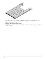
4. Remove the NSM module from the shelf:
a. Loop your index fingers through the finger holes of the latching mechanisms on either side of the NSM
module.
If you are removing the bottom NSM module, and if the bottom rail is obstructing access
to the latching mechanisms, place your index fingers through the finger holes from the
inside (by crossing your arms).
b. With your thumbs, press down and hold the orange tabs on top of the latching mechanisms.
The latching mechanisms raise, clearing the latching pins on the shelf.
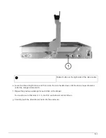
c. Gently pull until the NSM module is about one third of the way out of the shelf, grasp the NSM module
sides with both hands to support its weight, and then place it on a flat stable surface.
When you begin pulling, the latching mechanism arms extend from the NSM module and lock in their
fully extended position.
5. Unpack the replacement NSM module, and set it on a level surface near the impaired NSM module.
6. Open the cover of the impaired NSM module and the replacement NSM module by loosening the
thumbscrew on each cover.
The FRU label on the NSM module cover shows the location of the DIMMs and fans.
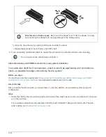
7. Move the DIMMs from the impaired NSM module to the replacement NSM module.
a. Note the orientation of the DIMMs in the slots so that you can insert the DIMMs into the replacement
NSM module using the same orientation.
b. Eject a DIMM from its slot by slowly pushing apart the ejector tabs at both ends of the DIMM slot, and
then lift the DIMM out of the slot.
Carefully hold the DIMM by the corners or edges to avoid pressure on the DIMM circuit
board components.
The ejector tabs remain in the open position.
c. Hold the DIMM by the corners, and then insert the DIMM squarely into a slot on the replacement NSM
module.
The notch on the bottom of the DIMM, among the pins, should line up with the tab in the slot.
When inserted correctly, the DIMM should go in easily but fit tightly in the slot. If not, reinsert the DIMM.
1532
Summary of Contents for AFF A700
Page 4: ...AFF and FAS System Documentation 1...
Page 208: ...3 Close the controller module cover and tighten the thumbscrew 205...
Page 248: ...2 Close the controller module cover and tighten the thumbscrew 245...
Page 308: ...Power supply Cam handle release latch Power and Fault LEDs Cam handle 305...
Page 381: ...Power supply Cam handle release latch Power and Fault LEDs Cam handle 378...
Page 437: ...1 Locate the DIMMs on your controller module 434...
Page 605: ...602...
Page 1117: ...3 Close the controller module cover and tighten the thumbscrew 1114...
Page 1157: ...2 Close the controller module cover and tighten the thumbscrew 1154...
Page 1228: ...Power supply Cam handle release latch Power and Fault LEDs Cam handle 1225...
Page 1300: ...Power supply Cam handle release latch Power and Fault LEDs Cam handle 1297...
Page 1462: ...Installing SuperRail to round hole four post rack 1459...
Page 1602: ...1599...
Page 1630: ...1627...
Page 1634: ...Orange ring on horizontal bracket Cable chain 1631...
Page 1645: ...Guide rail 1642...
Page 1669: ...Attention LED light on 1666...