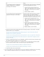

If…
Then…
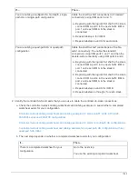
There is no completed worksheet for your
configuration
Fill out the appropriate controller-to-stack cabling
worksheet template:
Controller-to-stack cabling worksheet template for
multipathed connectivity
Controller-to-stack cabling worksheet template for
quad-pathed connectivity
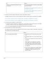
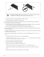
3. Cable the controller-to-stack connections using the completed worksheet.
If needed, instructions for how to read a worksheet to cable controller-to-stack connections are available:
How to read a worksheet to cable controller-to-stack connections for multipathed connectivity
How to read a worksheet to cable controller-to-stack connections for quad-pathed connectivity
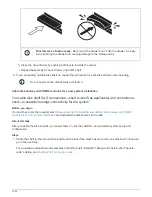
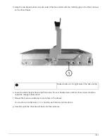
4. Connect the power supplies for each disk shelf:
a. Connect the power cords first to the disk shelves, securing them in place with the power cord retainer,
and then connect the power cords to different power sources for resiliency.
b. Turn on the power supplies for each disk shelf and wait for the disk drives to spin up.
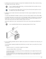
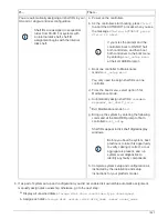
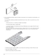
5. Set the shelf IDs and complete system setup:
You must set shelf IDs so they are unique within the HA pair or single-controller configuration, including the
internal disk shelf in applicable systems.
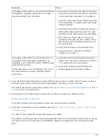
If…
Then…
You are manually setting shelf IDs
a. Access the shelf ID button behind the left end
cap.
b. Change the shelf ID to a unique ID (00 through
99).
c. Power-cycle the disk shelf to make the shelf ID
take effect.
Wait at least 10 seconds before turning the
power back on to complete the power cycle.
The shelf ID blinks and the operator display
panel amber LED blinks until you power cycle
the disk shelf.
d. Power on the controllers and complete system
setup and configuration as instructed by the
installation and setup instructions for your
platform model.
1546
Summary of Contents for AFF A700
Page 4: ...AFF and FAS System Documentation 1...
Page 208: ...3 Close the controller module cover and tighten the thumbscrew 205...
Page 248: ...2 Close the controller module cover and tighten the thumbscrew 245...
Page 308: ...Power supply Cam handle release latch Power and Fault LEDs Cam handle 305...
Page 381: ...Power supply Cam handle release latch Power and Fault LEDs Cam handle 378...
Page 437: ...1 Locate the DIMMs on your controller module 434...
Page 605: ...602...
Page 1117: ...3 Close the controller module cover and tighten the thumbscrew 1114...
Page 1157: ...2 Close the controller module cover and tighten the thumbscrew 1154...
Page 1228: ...Power supply Cam handle release latch Power and Fault LEDs Cam handle 1225...
Page 1300: ...Power supply Cam handle release latch Power and Fault LEDs Cam handle 1297...
Page 1462: ...Installing SuperRail to round hole four post rack 1459...
Page 1602: ...1599...
Page 1630: ...1627...
Page 1634: ...Orange ring on horizontal bracket Cable chain 1631...
Page 1645: ...Guide rail 1642...
Page 1669: ...Attention LED light on 1666...


