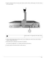
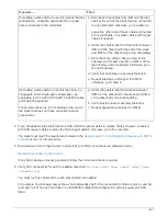
If…
Then…
You are automatically assigning all shelf IDs in your
HA pair or single-controller configuration
Shelf IDs are assigned in sequential
order from 00-99. For systems with
an internal disk shelf, shelf ID
assignment begins with the internal
disk shelf.
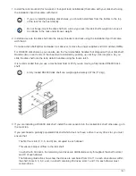
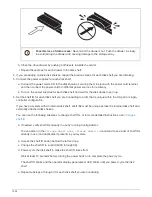
a. Power on the controllers.
b. As the controllers start booting, press
Ctrl-C
to abort the AUTOBOOT process when you see
the message
Starting AUTOBOOT press
Ctrl-C to abort
.
If you miss the prompt and the
controllers boot to ONTAP, halt
both controllers, and then boot
both controllers to the boot menu
by entering
boot_ontap menu
at their LOADER prompt.
c. Boot one controller to Maintenance
mode:
boot_ontap menu
You only need to assign shelf IDs on one
controller.
d. From the boot menu, select option 5 for
Maintenance mode.
e. Automatically assign shelf IDs:
sasadmin
expander_set_shelf_id -a
f. Exit Maintenance mode:
halt
g. Bring up the system by entering the following
command at the LOADER prompt of both
controllers:
boot_ontap
Shelf IDs appear in disk shelf digital display
windows.
Before you boot the system, best
practice is to take this opportunity
to verify cabling is correct, a root
aggregate is present, and run
system-level diagnostics to
identify any faulty components.
h. Complete system setup and configuration as
instructed by the installation and setup
instructions for your platform model.
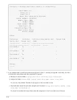
6. If as part of system set up and configuration, you did not enable disk ownership automatic assignment,
manually assign disk ownership; otherwise, go to the next step:
a. Display all unowned disks:
storage disk show -container-type unassigned
b. Assign each disk:
storage disk assign -disk
disk_name
-owner
owner_name
1547
Summary of Contents for AFF A700
Page 4: ...AFF and FAS System Documentation 1...
Page 208: ...3 Close the controller module cover and tighten the thumbscrew 205...
Page 248: ...2 Close the controller module cover and tighten the thumbscrew 245...
Page 308: ...Power supply Cam handle release latch Power and Fault LEDs Cam handle 305...
Page 381: ...Power supply Cam handle release latch Power and Fault LEDs Cam handle 378...
Page 437: ...1 Locate the DIMMs on your controller module 434...
Page 605: ...602...
Page 1117: ...3 Close the controller module cover and tighten the thumbscrew 1114...
Page 1157: ...2 Close the controller module cover and tighten the thumbscrew 1154...
Page 1228: ...Power supply Cam handle release latch Power and Fault LEDs Cam handle 1225...
Page 1300: ...Power supply Cam handle release latch Power and Fault LEDs Cam handle 1297...
Page 1462: ...Installing SuperRail to round hole four post rack 1459...
Page 1602: ...1599...
Page 1630: ...1627...
Page 1634: ...Orange ring on horizontal bracket Cable chain 1631...
Page 1645: ...Guide rail 1642...
Page 1669: ...Attention LED light on 1666...


