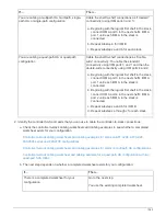
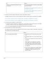
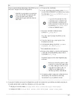
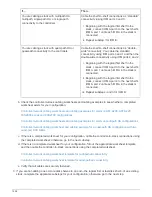
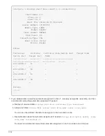


If…
Then…
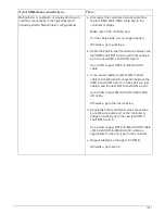
You are cabling a stack with multipath HA,
multipath, single-path HA, or single-path
connectivity to the controllers
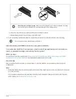
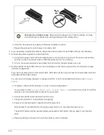
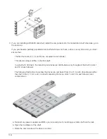
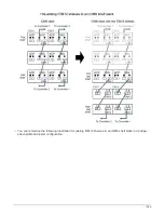
Cable the shelf-to-shelf connections as “standard”
connectivity (using IOM ports 3 and 1):
i. Beginning with the logical first shelf in the
stack, connect IOM A port 3 to the next shelf’s
IOM A port 1 until each IOM A in the stack is
connected.
ii. Repeat substep i for IOM B.
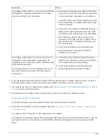
You are cabling a stack with quad-path HA or
quad-path connectivity to the controllers
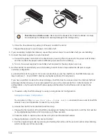
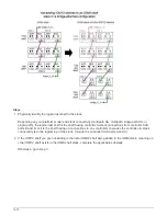
Cable the shelf-to-shelf connections as “double-
wide” connectivity: You cable the standard
connectivity using IOM ports 3 and 1 and then the
double-wide connectivity using IOM ports 4 and 2.
i. Beginning with the logical first shelf in the
stack, connect IOM A port 3 to the next shelf’s
IOM A port 1 until each IOM A in the stack is
connected.
ii. Beginning with the logical first shelf in the
stack, connect IOM A port 4 to the next shelf’s
IOM A port 2 until each IOM A in the stack is
connected.
iii. Repeat substeps i and ii for IOM B.
b. Check the controller-to-stack cabling worksheets and cabling examples to see whether a completed
worksheet exists for your configuration.
Controller-to-stack cabling worksheets and cabling examples for common multipath HA configurations
c. If there is a completed worksheet for your configuration, cable the controller-to-stack connections using
the completed worksheet; otherwise, go to the next substep.
d. If there is no completed worksheet for your configuration, fill out the appropriate worksheet template,
and then cable the controller-to-stack connections using the completed worksheet.
Controller-to-stack cabling worksheet template for multipathed connectivity
Controller-to-stack cabling worksheet template for quad-pathed connectivity
e. Verify that all cables are securely fastened.
3. If you are hot-adding one or more disk shelves to an end—the logical first or last disk shelf—of an existing
stack, complete the applicable substeps for your configuration; otherwise, go to the next step.
1556
Summary of Contents for AFF A700
Page 4: ...AFF and FAS System Documentation 1...
Page 208: ...3 Close the controller module cover and tighten the thumbscrew 205...
Page 248: ...2 Close the controller module cover and tighten the thumbscrew 245...
Page 308: ...Power supply Cam handle release latch Power and Fault LEDs Cam handle 305...
Page 381: ...Power supply Cam handle release latch Power and Fault LEDs Cam handle 378...
Page 437: ...1 Locate the DIMMs on your controller module 434...
Page 605: ...602...
Page 1117: ...3 Close the controller module cover and tighten the thumbscrew 1114...
Page 1157: ...2 Close the controller module cover and tighten the thumbscrew 1154...
Page 1228: ...Power supply Cam handle release latch Power and Fault LEDs Cam handle 1225...
Page 1300: ...Power supply Cam handle release latch Power and Fault LEDs Cam handle 1297...
Page 1462: ...Installing SuperRail to round hole four post rack 1459...
Page 1602: ...1599...
Page 1630: ...1627...
Page 1634: ...Orange ring on horizontal bracket Cable chain 1631...
Page 1645: ...Guide rail 1642...
Page 1669: ...Attention LED light on 1666...


