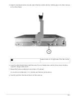
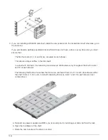

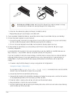
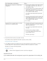

g. Power cycle the shelf to make the shelf ID take effect.
You must turn off both power switches, wait 10 seconds, and then turn them back on to complete the
power cycle.
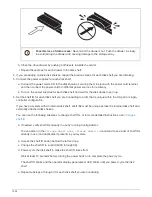
h. Repeat substeps b through g for each shelf you are hot-adding.
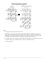
Cable shelves for a hot-add
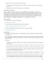
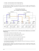
How you cable an IOM12 shelf to a stack of IOM6 shelves depends on whether the
IOM12 shelf is the initial IOM12 shelf, meaning no other IOM12 shelf exists in the stack,
or whether it is an additional IOM12 shelf to an existing mixed stack, meaning one or
more IOM12 shelves already exists in the stack. It also depends on whether the stack
has multipath HA, multipath, single-path HA, or single-path connectivity.
Before you begin
• You must have met the system requirements.
• You must have completed the preparation procedure, if applicable.
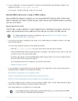
Prepare to manually assign drive ownership for a hot-add
• You must have installed the shelves, powered them on, and set the shelf IDs.
About this task
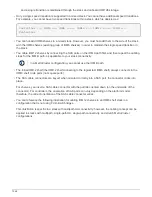
• You always hot-add IOM12 shelves to the logical last shelf in a stack to maintain a single speed transition
within the stack.
By hot-adding IOM12 shelves to the logical last shelf in a stack, the IOM6 shelves remain grouped together
and the IOM12 shelves remain grouped together so that there is a single speed transition between the two
groups of shelves.
For example:
◦
In an HA pair, a single speed transition within a stack having two IOM6 shelves and two IOM12 shelves
is depicted as:
Controller <-> IOM6 <-> IOM6 <---> IOM12 <-> IOM12 <-> Controller
◦
In an HA pair with onboard IOM12E storage, a single speed transition within a stack having two IOM12
shelves and two IOM6 shelves is depicted as:
IOM12E 0b <-> IOM12 <-> IOM12 <---> IOM6 <-> IOM6 <-> IOM12E 0a
The onboard storage port 0b is the port from the internal storage (expander) and because it connects
to the hot-added IOM12 shelf (the last shelf in the stack), the group of IOM12 shelves is kept together
1567
Summary of Contents for AFF A700
Page 4: ...AFF and FAS System Documentation 1...
Page 208: ...3 Close the controller module cover and tighten the thumbscrew 205...
Page 248: ...2 Close the controller module cover and tighten the thumbscrew 245...
Page 308: ...Power supply Cam handle release latch Power and Fault LEDs Cam handle 305...
Page 381: ...Power supply Cam handle release latch Power and Fault LEDs Cam handle 378...
Page 437: ...1 Locate the DIMMs on your controller module 434...
Page 605: ...602...
Page 1117: ...3 Close the controller module cover and tighten the thumbscrew 1114...
Page 1157: ...2 Close the controller module cover and tighten the thumbscrew 1154...
Page 1228: ...Power supply Cam handle release latch Power and Fault LEDs Cam handle 1225...
Page 1300: ...Power supply Cam handle release latch Power and Fault LEDs Cam handle 1297...
Page 1462: ...Installing SuperRail to round hole four post rack 1459...
Page 1602: ...1599...
Page 1630: ...1627...
Page 1634: ...Orange ring on horizontal bracket Cable chain 1631...
Page 1645: ...Guide rail 1642...
Page 1669: ...Attention LED light on 1666...


