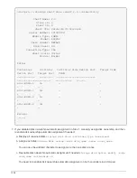
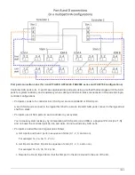

and a single transition is maintained through the stack and onboard IOM12E storage.
• Only a single speed transition is supported in a mixed stack. You cannot have additional speed transitions.
For example, you cannot have two speed transitions within a stack, which is depicted as:
Controller <-> IOM6 <-> IOM6 <---> IOM12 <-> IOM12 <---> IOM6 <->
Controller
• You can hot-add IOM6 shelves to a mixed stack. However, you must hot-add them to the side of the stack
with the IOM6 shelves (existing group of IOM6 shelves) in order to maintain the single speed transition in
the stack.
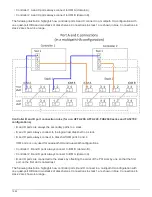
• You cable IOM12 shelves by connecting the SAS ports on the IOM A path first, and then repeat the cabling
steps for the IOM B path, as applicable to your stack connectivity.
In a MetroCluster configuration, you cannot use the IOM B path.
• The initial IOM12 shelf (the IOM12 shelf connecting to the logical last IOM6 shelf) always connects to the
IOM6 shelf circle ports (not square ports).
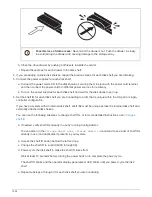
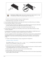
• The SAS cable connectors are keyed; when oriented correctly into a SAS port, the connector clicks into
place.
For shelves, you insert a SAS cable connector with the pull tab oriented down (on the underside of the
connector). For controllers, the orientation of SAS ports can vary depending on the platform model;
therefore, the correct orientation of the SAS cable connector varies.
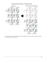
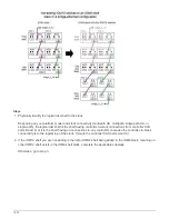
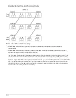
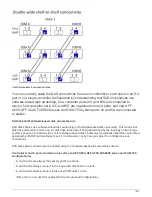
• You can reference the following illustration for cabling IOM12 shelves to an IOM6 shelf stack in a
configuration that is not using FC-to-SAS bridges.
This illustration is specific to a stack with multipath HA connectivity; however, the cabling concept can be
applied to stacks with multipath, single-path HA, single-path connectivity, and stretch MetroCluster
configurations.
1568
Summary of Contents for AFF A700
Page 4: ...AFF and FAS System Documentation 1...
Page 208: ...3 Close the controller module cover and tighten the thumbscrew 205...
Page 248: ...2 Close the controller module cover and tighten the thumbscrew 245...
Page 308: ...Power supply Cam handle release latch Power and Fault LEDs Cam handle 305...
Page 381: ...Power supply Cam handle release latch Power and Fault LEDs Cam handle 378...
Page 437: ...1 Locate the DIMMs on your controller module 434...
Page 605: ...602...
Page 1117: ...3 Close the controller module cover and tighten the thumbscrew 1114...
Page 1157: ...2 Close the controller module cover and tighten the thumbscrew 1154...
Page 1228: ...Power supply Cam handle release latch Power and Fault LEDs Cam handle 1225...
Page 1300: ...Power supply Cam handle release latch Power and Fault LEDs Cam handle 1297...
Page 1462: ...Installing SuperRail to round hole four post rack 1459...
Page 1602: ...1599...
Page 1630: ...1627...
Page 1634: ...Orange ring on horizontal bracket Cable chain 1631...
Page 1645: ...Guide rail 1642...
Page 1669: ...Attention LED light on 1666...