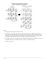

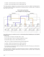
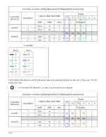

For example:
Offsetting the order of the slots by one balances port pairs across multiple slots (physical PCI slots and
on board slots) when more than one slot of SAS ports is available; therefore, preventing a stack from
being cabled to a single SAS HBA.
d. Pair the A and C ports (listed in step 1) to the D and B ports (listed in step 2) in the order that they are
listed.
For example: 1a/2b, 2a/3b, 3a/1d,1c/2d, 2c/3d, 3c/1b.
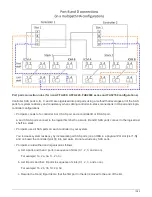
For an HA pair, the list of port pairs you identify for the first controller is also applicable to
the second controller.
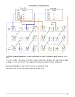
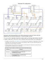
• When cabling your system, you can use port pairs in the order in which you identified them or you can skip
port pairs:
◦
Use port pairs in the order in which you identified (listed) them when all port pairs are needed to cable
the stacks in your system.
For example, if you identified six port pairs for your system and you have six stacks to cable as
multipath, you cable the port pairs in the order in which you listed them:
1a/2b, 2a/3b, 3a/1d,1c/2d, 2c/3d, 3c/1b
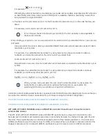
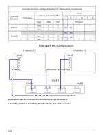
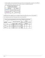
◦
Skip port pairs (use every other port pair) when not all port pairs are needed to cable the stacks in your
system.
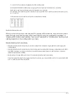
For example, if you identified six port pairs for your system and you have three stacks to cable as
multipath, you cable every other port pair in your list:
When you have more port pairs than you need to cable the stacks in your system, the
best practice is to skip port pairs to optimize the SAS ports on your system. By
optimizing SAS ports, you optimize your system’s performance.
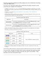
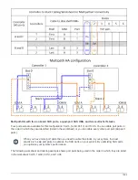
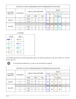
Controller-to-stack cabling worksheets are convenient tools for identifying and organizing port pairs so that you
can cable the controller-to-stack connections for your HA pair or single-controller configuration.
Controller-to-stack cabling worksheet template for multipathed connectivity
Controller-to-stack cabling worksheet template for quad-pathed connectivity
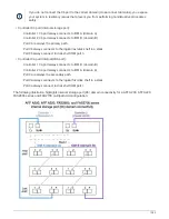
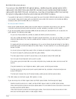
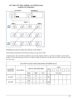
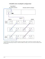
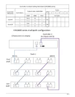
AFF A200, AFF A220, FAS2600 series and FAS2700 controller 0b and 0a port connection rules to
external disk shelves
The AFF A200, AFF A220, FAS2600 series and FAS2700 systems have a unique set of connection rules
because each controller must maintain same domain connectivity between the internal storage (port 0b) and
the stack. This means that when a controller is located in slot A of the chassis (controller 1) it is in domain A
(IOM A) and therefore port 0b must connect to IOM A in the stack. When a controller is located in slot B of the
chassis (controller 2) it is in domain B (IOM B) and therefore port 0b must connect to IOM B in the stack.
1584
Summary of Contents for AFF A700
Page 4: ...AFF and FAS System Documentation 1...
Page 208: ...3 Close the controller module cover and tighten the thumbscrew 205...
Page 248: ...2 Close the controller module cover and tighten the thumbscrew 245...
Page 308: ...Power supply Cam handle release latch Power and Fault LEDs Cam handle 305...
Page 381: ...Power supply Cam handle release latch Power and Fault LEDs Cam handle 378...
Page 437: ...1 Locate the DIMMs on your controller module 434...
Page 605: ...602...
Page 1117: ...3 Close the controller module cover and tighten the thumbscrew 1114...
Page 1157: ...2 Close the controller module cover and tighten the thumbscrew 1154...
Page 1228: ...Power supply Cam handle release latch Power and Fault LEDs Cam handle 1225...
Page 1300: ...Power supply Cam handle release latch Power and Fault LEDs Cam handle 1297...
Page 1462: ...Installing SuperRail to round hole four post rack 1459...
Page 1602: ...1599...
Page 1630: ...1627...
Page 1634: ...Orange ring on horizontal bracket Cable chain 1631...
Page 1645: ...Guide rail 1642...
Page 1669: ...Attention LED light on 1666...