You can use your completed worksheet to cable your system.
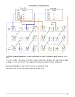
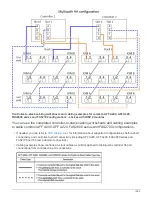
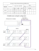
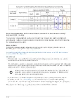
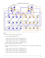
Controller-to-stack cabling worksheet template for quad-pathed connectivity - shelves with IOM12
modules
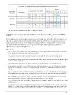
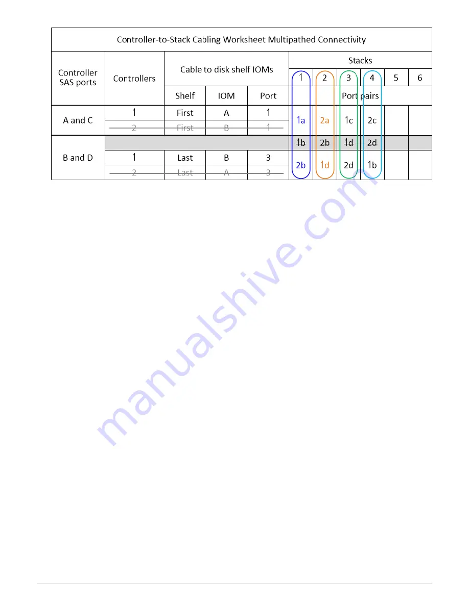
By completing the worksheet template, you can define the controller SAS port pairs you
can use to cable controllers to stacks of disk shelves with IOM12 modules to achieve
quad-pathed connectivity in an HA pair or single-controller configuration. You can also
use the completed worksheet to walk yourself through cabling the quad-pathed
connections for your configuration.
About his task
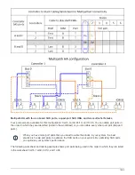
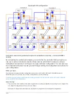
• This procedure and worksheet template is applicable to cabling quad-pathed connectivity for a quad-path
HA or quad-path configuration with one or more stacks.
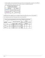
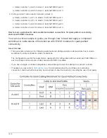
Examples of completed worksheets are provided for quad-path HA and quad-path configurations.
A configuration with two quad-port SAS HBAs and two stacks of disk shelves with IOM12 modules is used
for the worksheet examples.
• The worksheet template allows for up to two stacks; you need to add more columns if needed.
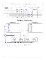
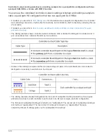
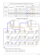
• Quad-pathed connectivity for controller-to-stack connections consists of two sets of multipathed cabling:
the first set of cabling is referred to as “multipathed”; the second set of cabling is referred to as “quad-
pathed”.
The second set of cabling is referred to as “quad-pathed” because completing this set of cabling gives you
the quad-pathed connectivity from a controller to a stack in an HA pair or single-controller configuration.
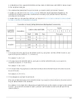
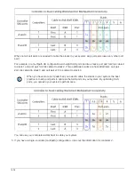
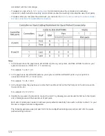
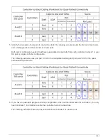
• Disk shelf IOM ports 1 and 3 are always used for multipathed cabling and IOM ports 2 and 4 are always
used for quad-pathed cabling, as designated by the worksheet column headings.
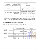
• In the worksheet examples, port pairs are designated for multipathed cabling or quad-pathed cabling to the
applicable stack.
Each port pair designated for multipathed cabling is encircled by an oval that is the color associated with
the stack it is cabled to. Each port pair designated for quad-pathed cabling is encircled by a rectangle that
is the color associated with the stack it is cabled to. Stack 1 is associated with the color blue; stack 2 is
1605
Summary of Contents for AFF A700
Page 4: ...AFF and FAS System Documentation 1...
Page 208: ...3 Close the controller module cover and tighten the thumbscrew 205...
Page 248: ...2 Close the controller module cover and tighten the thumbscrew 245...
Page 308: ...Power supply Cam handle release latch Power and Fault LEDs Cam handle 305...
Page 381: ...Power supply Cam handle release latch Power and Fault LEDs Cam handle 378...
Page 437: ...1 Locate the DIMMs on your controller module 434...
Page 605: ...602...
Page 1117: ...3 Close the controller module cover and tighten the thumbscrew 1114...
Page 1157: ...2 Close the controller module cover and tighten the thumbscrew 1154...
Page 1228: ...Power supply Cam handle release latch Power and Fault LEDs Cam handle 1225...
Page 1300: ...Power supply Cam handle release latch Power and Fault LEDs Cam handle 1297...
Page 1462: ...Installing SuperRail to round hole four post rack 1459...
Page 1602: ...1599...
Page 1630: ...1627...
Page 1634: ...Orange ring on horizontal bracket Cable chain 1631...
Page 1645: ...Guide rail 1642...
Page 1669: ...Attention LED light on 1666...