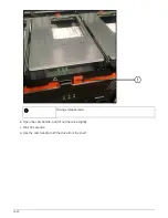
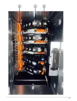

A disk shelf has three location LEDs: one on the operator display panel and one on each IOM12 module.
Location LEDs remain illuminated for 30 minutes. You can turn them off by entering the same command,
but using the off option.
• If needed, you can refer to the Monitoring disk shelf LEDs section for information about the meaning and
location of disk shelf LEDs on the operator display panel and FRU components.
Steps
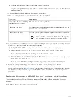
1. If you want to manually assign disk ownership for the replacement disk drive, you need to disable
automatic drive assignment if it is enabled; otherwise, go to the next step.
You need to manually assign disk ownership if disk drives in the stack are owned by both
controllers in an HA pair.
You manually assign disk ownership and then reenable automatic drive assignment later in
this procedure.
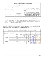
a. Verify if automatic drive assignment is enabled:
storage disk option show
If you have an HA pair, you can enter the command at the console of either controller.
If automatic drive assignment is enabled, the output shows “on” (for each controller) in the “Auto
Assign” column.
b. If automatic drive assignment is enabled, you need to disable it:
storage disk option modify
-node
node_name
-autoassign off
You need to disable automatic drive assignment on both controllers in an HA pair.
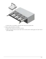
2. Properly ground yourself.
3. Unpack the new disk drive, and set it on a level surface near the disk shelf.
Save all packaging materials for use when returning the failed disk drive.
NetApp requires that all returned disk drives be in a ESD-rated bag.
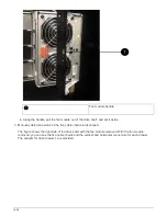
4. Physically identify the failed disk drive from the system console warning message and the illuminated
attention (amber) LED on the disk drive.
The activity (green) LED on a failed disk drive can be illuminated (solid), which indicates the
disk drive has power, but should not be blinking, which indicates I/O activity. A failed disk
drive has no I/O activity.
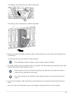
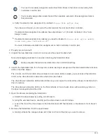
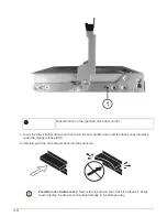
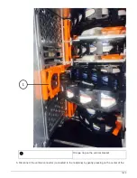
5. Press the release button on the disk drive face, and then pull the cam handle to its fully open position to
release the disk drive from the mid plane.
When you press the release button, the cam handle on the disk drive springs open partially.
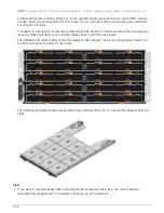
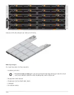
Disk drives in a DS212C disk shelf are arranged horizontally with the release button located
on the left of the disk drive face. Disk drives in a DS224C disk shelf are arranged vertically
with the release button located at the top of the disk drive face.
1614
Summary of Contents for AFF A700
Page 4: ...AFF and FAS System Documentation 1...
Page 208: ...3 Close the controller module cover and tighten the thumbscrew 205...
Page 248: ...2 Close the controller module cover and tighten the thumbscrew 245...
Page 308: ...Power supply Cam handle release latch Power and Fault LEDs Cam handle 305...
Page 381: ...Power supply Cam handle release latch Power and Fault LEDs Cam handle 378...
Page 437: ...1 Locate the DIMMs on your controller module 434...
Page 605: ...602...
Page 1117: ...3 Close the controller module cover and tighten the thumbscrew 1114...
Page 1157: ...2 Close the controller module cover and tighten the thumbscrew 1154...
Page 1228: ...Power supply Cam handle release latch Power and Fault LEDs Cam handle 1225...
Page 1300: ...Power supply Cam handle release latch Power and Fault LEDs Cam handle 1297...
Page 1462: ...Installing SuperRail to round hole four post rack 1459...
Page 1602: ...1599...
Page 1630: ...1627...
Page 1634: ...Orange ring on horizontal bracket Cable chain 1631...
Page 1645: ...Guide rail 1642...
Page 1669: ...Attention LED light on 1666...


