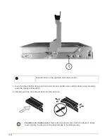
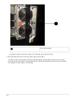
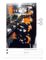
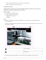
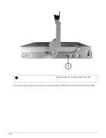
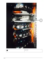


b. Gently insert your finger into the orange ring.
The figure shows the orange ring on the horizontal bracket being pushed down so that the rest of the
cable chain can be pulled out of the enclosure.
c. Pull your finger toward you to unplug the cable chain.
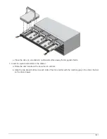
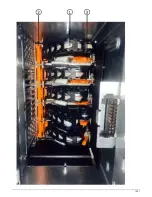
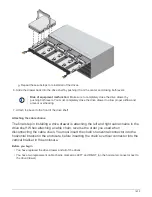
7. Carefully pull the entire cable chain out of the drive shelf.
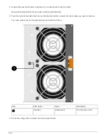
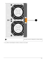
8. From the back of the drive shelf, remove the left fan module.
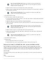
9. Follow these steps to disconnect the left cable chain from its vertical bracket:
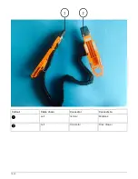
a. Using a flashlight, locate the orange ring on the end of the cable chain attached to the vertical bracket.
b. Insert your finger into the orange ring.
c. To unplug the cable chain, pull your finger toward you approximately 1 inch (2.5 cm), but leave the
cable chain connector within the vertical bracket.
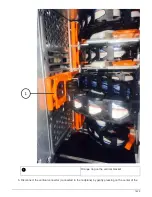
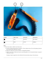
10. Disconnect the left cable chain from the horizontal bracket, and pull the entire cable chain out of the drive
shelf.
Removing a drive drawer
After removing the right and left cable chains, you can remove the drive drawer from the
drive shelf. Removing a drive drawer entails sliding the drawer part of the way out,
recording the locations of the drives, removing the drives, and removing the drive drawer.
Before you begin
• You have removed the right and left cable chains for the drive drawer.
• You have replaced the right and left fan modules.
• You have obtained a permanent marker to note the exact location of each drive as you remove the drive
from the drawer.
Steps
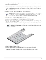
1. Remove the bezel from the front of the drive shelf.
2. Unlatch the drive drawer by pulling out on both levers.
3. Using the extended levers, carefully pull the drive drawer out until it stops. Do not completely remove the
drive drawer from the drive shelf.
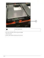
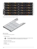
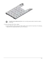
4. If logical unit numbers (LUNs) have already been created and assigned, use a permanent marker to note
the exact location of each drive. For example, using the following drawing as a reference, write the
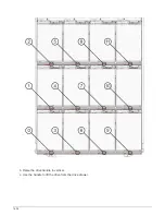
appropriate slot number on the top of each drive.
1632
Summary of Contents for AFF A700
Page 4: ...AFF and FAS System Documentation 1...
Page 208: ...3 Close the controller module cover and tighten the thumbscrew 205...
Page 248: ...2 Close the controller module cover and tighten the thumbscrew 245...
Page 308: ...Power supply Cam handle release latch Power and Fault LEDs Cam handle 305...
Page 381: ...Power supply Cam handle release latch Power and Fault LEDs Cam handle 378...
Page 437: ...1 Locate the DIMMs on your controller module 434...
Page 605: ...602...
Page 1117: ...3 Close the controller module cover and tighten the thumbscrew 1114...
Page 1157: ...2 Close the controller module cover and tighten the thumbscrew 1154...
Page 1228: ...Power supply Cam handle release latch Power and Fault LEDs Cam handle 1225...
Page 1300: ...Power supply Cam handle release latch Power and Fault LEDs Cam handle 1297...
Page 1462: ...Installing SuperRail to round hole four post rack 1459...
Page 1602: ...1599...
Page 1630: ...1627...
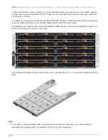
Page 1634: ...Orange ring on horizontal bracket Cable chain 1631...
Page 1645: ...Guide rail 1642...
Page 1669: ...Attention LED light on 1666...


