


cluster::> storage disk show -shelf 3
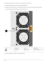
Usable Disk Container Container
Disk Size Shelf Bay Type Type Name Owner
-------- -------- ----- --- ------ ----------- ---------- ---------
...
1.3.4 - 3 4 SAS spare - -
1.3.5 - 3 5 SAS spare - -
1.3.6 - 3 6 SAS broken - -
1.3.7 - 3 7 SAS spare - -
...
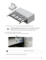
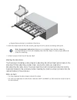
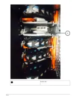
1. Physically locate the disk shelves you are removing.
If needed, you can turn on the disk shelf’s location (blue) LEDs to aid in physically locating the affected disk
shelf:
storage shelf location-led modify -shelf-name
shelf_name
-led-status on
A disk shelf has three location LEDs: one on the operator display panel and one on each
IOM12 module. Location LEDs remain illuminated for 30 minutes. You can turn them off by
entering the same command, but using the off option.
2. If you are removing an entire stack of disk shelves, complete the following substeps; otherwise, go to the
next step:
a. Remove all SAS cables on path A (IOM A) and path B (IOM B).
This includes controller-to-shelf cables and shelf-to-shelf cables for all disk shelves in the stack you are
removing.
b. Go to step 9.
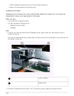
3. If you are removing one or more disk shelves from a stack (but keeping the stack), recable the path A (IOM
A) stack connections to bypass the disk shelves you are removing by completing the applicable set of
substeps:
If you are removing more than one disk shelf in the stack, complete the applicable set of substeps one disk
shelf at a time.
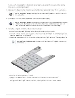
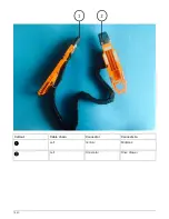
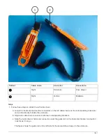
Wait at least 10 seconds before connecting the port. The SAS cable connectors are keyed;
when oriented correctly into a SAS port, the connector clicks into place and the disk shelf
SAS port LNK LED illuminates green. For disk shelves, you insert a SAS cable connector
with the pull tab oriented down (on the underside of the connector).
1649
Summary of Contents for AFF A700
Page 4: ...AFF and FAS System Documentation 1...
Page 208: ...3 Close the controller module cover and tighten the thumbscrew 205...
Page 248: ...2 Close the controller module cover and tighten the thumbscrew 245...
Page 308: ...Power supply Cam handle release latch Power and Fault LEDs Cam handle 305...
Page 381: ...Power supply Cam handle release latch Power and Fault LEDs Cam handle 378...
Page 437: ...1 Locate the DIMMs on your controller module 434...
Page 605: ...602...
Page 1117: ...3 Close the controller module cover and tighten the thumbscrew 1114...
Page 1157: ...2 Close the controller module cover and tighten the thumbscrew 1154...
Page 1228: ...Power supply Cam handle release latch Power and Fault LEDs Cam handle 1225...
Page 1300: ...Power supply Cam handle release latch Power and Fault LEDs Cam handle 1297...
Page 1462: ...Installing SuperRail to round hole four post rack 1459...
Page 1602: ...1599...
Page 1630: ...1627...
Page 1634: ...Orange ring on horizontal bracket Cable chain 1631...
Page 1645: ...Guide rail 1642...
Page 1669: ...Attention LED light on 1666...


