


• If needed, you can turn on the disk shelf’s location (blue) LEDs to aid in physically locating the affected disk
shelf:
storage shelf location-led modify -shelf-name
shelf_name
-led-status on
A disk shelf has three location LEDs: one on the operator display panel and one on each IOM12 module.
Location LEDs remain illuminated for 30 minutes. You can turn them off by entering the same command,
but using the off option.
• If needed, you can refer to the Monitoring disk shelf LEDs section for information about the meaning and
location of disk shelf LEDs on the operator display panel and FRU components.
Steps
1. Properly ground yourself.
2. Unpack the new IOM12 module, and set it on a level surface near the disk shelf.
Save all packaging materials for use when returning the failed IOM12 module.
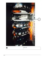
3. Physically identify the failed IOM12 module from the system console warning message and the illuminated
attention (amber) LED on the failed IOM12 module.
4. Perform one of the following actions based on the type of configuration you have:
If you have a…
Then…
Multipath HA, multipath, quad-path HA, or quad-
path configuration
Go to the next step.
FAS2600 series and FAS2700 single-path HA
configuration
a. Determine the target node (the node the failed
IOM12 module belongs to).
IOM A belongs to Controller 1. IOM B belongs
to Controller 2.
b. Take over the target node:
storage
failover takeover -bynode
partner
HA node
FAS2600 series single-path configuration
a. Shut down the system from the system console:
halt
b. Verify that your system halted by checking the
storage system console.
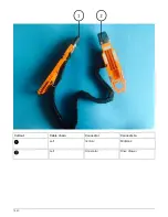
5. Disconnect the cabling from the IOM12 module that you are removing.
Make note of the IOM12 module ports each cable is connected to.
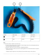
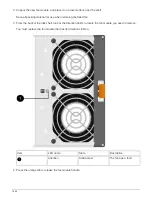
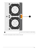
6. Press the orange latch on the IOM12 module cam handle until it releases, and then open the cam handle
fully to release the IOM12 module from the mid plane.
1654
Summary of Contents for AFF A700
Page 4: ...AFF and FAS System Documentation 1...
Page 208: ...3 Close the controller module cover and tighten the thumbscrew 205...
Page 248: ...2 Close the controller module cover and tighten the thumbscrew 245...
Page 308: ...Power supply Cam handle release latch Power and Fault LEDs Cam handle 305...
Page 381: ...Power supply Cam handle release latch Power and Fault LEDs Cam handle 378...
Page 437: ...1 Locate the DIMMs on your controller module 434...
Page 605: ...602...
Page 1117: ...3 Close the controller module cover and tighten the thumbscrew 1114...
Page 1157: ...2 Close the controller module cover and tighten the thumbscrew 1154...
Page 1228: ...Power supply Cam handle release latch Power and Fault LEDs Cam handle 1225...
Page 1300: ...Power supply Cam handle release latch Power and Fault LEDs Cam handle 1297...
Page 1462: ...Installing SuperRail to round hole four post rack 1459...
Page 1602: ...1599...
Page 1630: ...1627...
Page 1634: ...Orange ring on horizontal bracket Cable chain 1631...
Page 1645: ...Guide rail 1642...
Page 1669: ...Attention LED light on 1666...


