


1. Properly ground yourself.
2. Unpack the new power supply and set it on a level surface near the shelf.
Save all packing materials for use when returning the failed power supply.
3. Physically identify the failed power supply from the system console warning message and the illuminated
attention (amber) LED on the power supply.
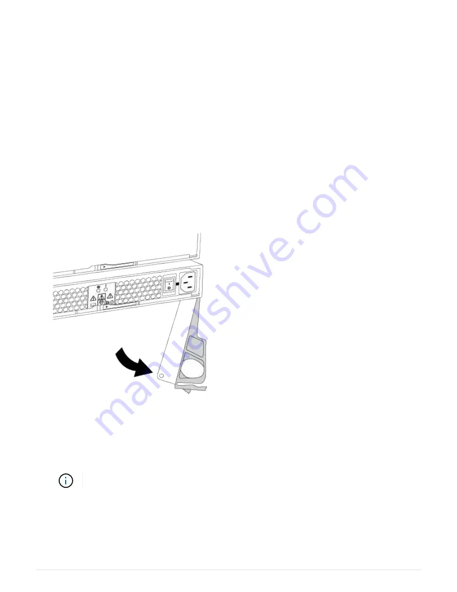
4. Turn off the failed power supply and disconnect the power cable:
a. Turn off the power switch on the power supply.
b. Open the power cord retainer and unplug the power cord from the power supply.
c. Unplug the power cord from the power source.
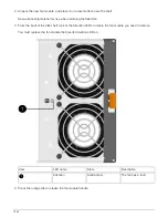
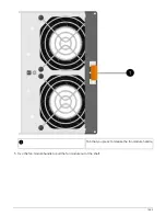
5. Press the orange latch on the power supply cam handle until it releases, and then open the cam handle to
fully release the power supply from the mid plane.
The following illustration is for a power supply used in a DS224C or DS212C disk shelf; however, the latch
operates the same way for power supplies used in DS460C disk shelves.
6. Use the cam handle to slide the power supply out of the disk shelf.
If you have a DS224C or DS212C disk shelf, as you remove the power supply, a flap swings into place to
block the empty bay, helping to maintain air flow and cooling.
When handling a power supply, always use two hands to support its weight.
7. Make sure that the on/off switch of the new power supply is in the Off position.
8. Using two hands, with the cam handle of the new power supply in the open position, support and align the
edges of the new power supply with the opening in the disk shelf, and then firmly push the new power
supply until it meets the mid plane.
1657
Summary of Contents for AFF A700
Page 4: ...AFF and FAS System Documentation 1...
Page 208: ...3 Close the controller module cover and tighten the thumbscrew 205...
Page 248: ...2 Close the controller module cover and tighten the thumbscrew 245...
Page 308: ...Power supply Cam handle release latch Power and Fault LEDs Cam handle 305...
Page 381: ...Power supply Cam handle release latch Power and Fault LEDs Cam handle 378...
Page 437: ...1 Locate the DIMMs on your controller module 434...
Page 605: ...602...
Page 1117: ...3 Close the controller module cover and tighten the thumbscrew 1114...
Page 1157: ...2 Close the controller module cover and tighten the thumbscrew 1154...
Page 1228: ...Power supply Cam handle release latch Power and Fault LEDs Cam handle 1225...
Page 1300: ...Power supply Cam handle release latch Power and Fault LEDs Cam handle 1297...
Page 1462: ...Installing SuperRail to round hole four post rack 1459...
Page 1602: ...1599...
Page 1630: ...1627...
Page 1634: ...Orange ring on horizontal bracket Cable chain 1631...
Page 1645: ...Guide rail 1642...
Page 1669: ...Attention LED light on 1666...


