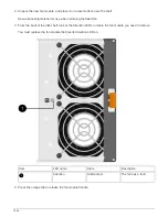


Do not use excessive force when sliding the power supply into the disk shelf; you might
damage the connectors.
9. Close the cam handle so that the latch clicks into the locked position and the power supply is fully seated.
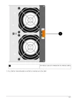
10. Reconnect the power supply cable and turn on the new power supply:
a. Reconnect the power cord to the power source.
b. Reconnect the power cord to the power supply and secure the power cord with the power cord retainer.
c. Turn on the power switch.
The power supply’s power (green) LED and attention (amber) LED illuminate, and then within 40
seconds, the attention (amber) LED turns off.
11. Return the failed part to NetApp, as described in the RMA instructions shipped with the kit.
Contact technical support at
, 888-463-8277 (North America), 00-800-44-638277 (Europe),
or +800-800-80-800 (Asia/Pacific) if you need the RMA number or additional help with the replacement
procedure.
Monitor disk shelf LEDs - shelves with IOM12 modules
You can monitor the health of your disk shelf by understanding the location and status
conditions of the LEDs on your disk shelf components.
Operator display panel LEDs
The LEDs on the disk shelf front operator display panel indicate whether your disk shelf is
functioning normally or there are problems with the hardware.
The following table describes the three LEDs on the operator display panel used in DS460C, DS224C, and
DS212C disk shelves:
LED icon
LED name
State
Description
Power
Solid green
One or more power
supplies are supplying
power to the disk shelf.
1658
Summary of Contents for AFF A700
Page 4: ...AFF and FAS System Documentation 1...
Page 208: ...3 Close the controller module cover and tighten the thumbscrew 205...
Page 248: ...2 Close the controller module cover and tighten the thumbscrew 245...
Page 308: ...Power supply Cam handle release latch Power and Fault LEDs Cam handle 305...
Page 381: ...Power supply Cam handle release latch Power and Fault LEDs Cam handle 378...
Page 437: ...1 Locate the DIMMs on your controller module 434...
Page 605: ...602...
Page 1117: ...3 Close the controller module cover and tighten the thumbscrew 1114...
Page 1157: ...2 Close the controller module cover and tighten the thumbscrew 1154...
Page 1228: ...Power supply Cam handle release latch Power and Fault LEDs Cam handle 1225...
Page 1300: ...Power supply Cam handle release latch Power and Fault LEDs Cam handle 1297...
Page 1462: ...Installing SuperRail to round hole four post rack 1459...
Page 1602: ...1599...
Page 1630: ...1627...
Page 1634: ...Orange ring on horizontal bracket Cable chain 1631...
Page 1645: ...Guide rail 1642...
Page 1669: ...Attention LED light on 1666...


