


The target port you configure is the target port you use to communicate with the
impaired node from the healthy node during var file system restore with a network
connection. You can also use the e0M port in this command.
◦
If you are configuring manual connections:
ifconfig e0a -addr=filer_addr -mask=netmask
-gw=gateway-dns=dns_addr-domain=dns_domain
▪
filer_addr
is the IP address of the storage system.
▪
netmask
is the network mask of the management network that is connected to the HA partner.
▪
gateway
is the gateway for the network.
▪
dns_addr
is the IP address of a name server on your network.
▪
dns_domain
is the Domain Name System (DNS) domain name.
If you use this optional parameter, you do not need a fully qualified domain name in the netboot
server URL. You need only the server’s host name.
Other parameters might be necessary for your interface. You can enter
help ifconfig
at
the firmware prompt for details.
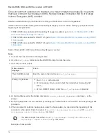
Boot the recovery image - AFF A200
You must boot the ONTAP image from the USB drive, restore the file system, and verify
the environmental variables.
Steps
1. From the LOADER prompt, boot the recovery image from the USB flash drive:
boot_recovery
The image is downloaded from the USB flash drive.
2. When prompted, either enter the name of the image or accept the default image displayed inside the
brackets on your screen.
3. Restore the
var
file system:
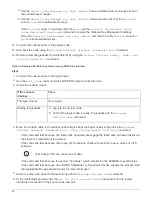
If your system has…
Then…
A network connection
a. Press
y
when prompted to restore the backup configuration.
b. Set the healthy node to advanced privilege level:
set
-privilege advanced
c. Run the restore backup command:
system node restore-
backup -node local -target-address
impaired_node_IP_address
d. Return the node to admin level:
set -privilege admin
e. Press
y
when prompted to use the restored configuration.
f. Press
y
when prompted to reboot the node.
14
Summary of Contents for AFF A700
Page 4: ...AFF and FAS System Documentation 1...
Page 208: ...3 Close the controller module cover and tighten the thumbscrew 205...
Page 248: ...2 Close the controller module cover and tighten the thumbscrew 245...
Page 308: ...Power supply Cam handle release latch Power and Fault LEDs Cam handle 305...
Page 381: ...Power supply Cam handle release latch Power and Fault LEDs Cam handle 378...
Page 437: ...1 Locate the DIMMs on your controller module 434...
Page 605: ...602...
Page 1117: ...3 Close the controller module cover and tighten the thumbscrew 1114...
Page 1157: ...2 Close the controller module cover and tighten the thumbscrew 1154...
Page 1228: ...Power supply Cam handle release latch Power and Fault LEDs Cam handle 1225...
Page 1300: ...Power supply Cam handle release latch Power and Fault LEDs Cam handle 1297...
Page 1462: ...Installing SuperRail to round hole four post rack 1459...
Page 1602: ...1599...
Page 1630: ...1627...
Page 1634: ...Orange ring on horizontal bracket Cable chain 1631...
Page 1645: ...Guide rail 1642...
Page 1669: ...Attention LED light on 1666...


