

As you insert the connector, you should feel it click into place; if you do not feel it click, remove
it, turn it around and try again.
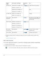
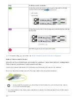
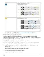
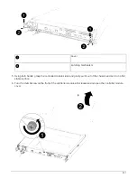
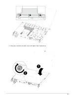
Step
Perform on each controller module
1
Cable ports 2a through 2d to the FC host
switches.
2
To perform other optional cabling, choose from:
•
Option 2: Cable to a 25GbE data or host network
•
Option 3: Cable the controllers to a single drive shelf
3
To complete setting up your system, see
.
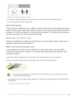
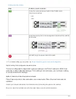
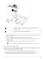
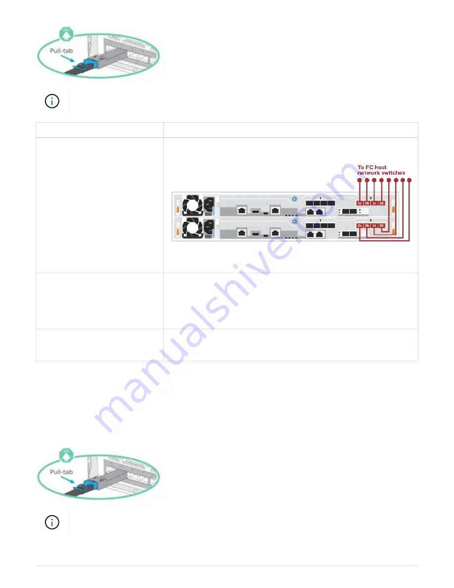
Option 2: Cable to a 25GbE data or host network
25GbE ports on the controllers are connected to 25GbE data or host network switches.
Contact your network administrator for information about connecting the system to the switches.
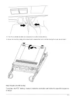
Be sure to check the illustration arrow for the proper cable connector pull-tab orientation.
As you insert the connector, you should feel it click into place; if you do not feel it click, remove
it, turn it around and try again.
190
Summary of Contents for AFF A700
Page 4: ...AFF and FAS System Documentation 1...
Page 208: ...3 Close the controller module cover and tighten the thumbscrew 205...
Page 248: ...2 Close the controller module cover and tighten the thumbscrew 245...
Page 308: ...Power supply Cam handle release latch Power and Fault LEDs Cam handle 305...
Page 381: ...Power supply Cam handle release latch Power and Fault LEDs Cam handle 378...
Page 437: ...1 Locate the DIMMs on your controller module 434...
Page 605: ...602...
Page 1117: ...3 Close the controller module cover and tighten the thumbscrew 1114...
Page 1157: ...2 Close the controller module cover and tighten the thumbscrew 1154...
Page 1228: ...Power supply Cam handle release latch Power and Fault LEDs Cam handle 1225...
Page 1300: ...Power supply Cam handle release latch Power and Fault LEDs Cam handle 1297...
Page 1462: ...Installing SuperRail to round hole four post rack 1459...
Page 1602: ...1599...
Page 1630: ...1627...
Page 1634: ...Orange ring on horizontal bracket Cable chain 1631...
Page 1645: ...Guide rail 1642...
Page 1669: ...Attention LED light on 1666...