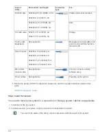

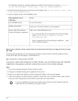

The following AutoSupport message suppresses automatic case creation for two hours:
cluster1:*>
system node autosupport invoke -node * -type all -message MAINT=2h
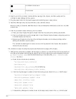
2. Disable automatic giveback from the console of the healthy node:
storage failover modify –node
local -auto-giveback false
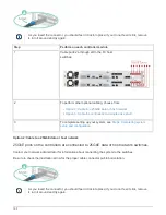
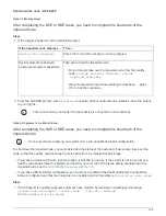
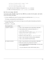
3. Take the impaired node to the LOADER prompt:
If the impaired node is
displaying…
Then…
The LOADER prompt
Go to the next step.
Waiting for giveback…
Press Ctrl-C, and then respond
y
when prompted.
System prompt or password
prompt (enter system password)
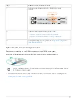
Take over or halt the impaired node:
• For an HA pair, take over the impaired node from the healthy
node:
storage failover takeover -ofnode
impaired_node_name
When the impaired node shows Waiting for giveback…, press
Ctrl-C, and then respond
y
.
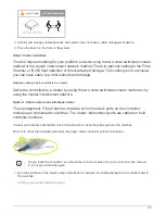
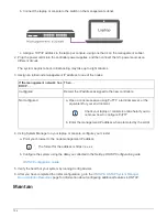
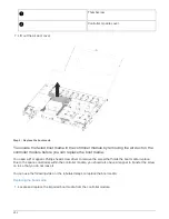
Remove the controller module, replace the boot media and transfer the boot image to the boot media -
AFF A250
To replace the boot media, you must remove the impaired controller module, install the replacement boot
media, and transfer the boot image to a USB flash drive.
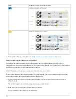
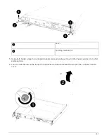
Step 1: Remove the controller module - AFF A250
To access components inside the controller module, you must first remove the controller
module from the system, and then remove the cover on the controller module.
Steps
1. If you are not already grounded, properly ground yourself.
2. Unplug the controller module power supplies from the source.
3. Release the power cable retainers, and then unplug the cables from the power supplies.
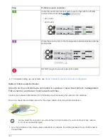
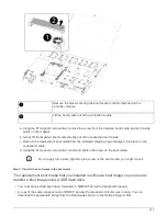
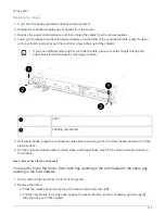
4. Insert your forefinger into the latching mechanism on either side of the controller module, press the lever
with your thumb, and gently pull the controller a few inches out of the chassis.
If you have difficulty removing the controller module, place your index fingers through the
finger holes from the inside (by crossing your arms)
200
Summary of Contents for AFF A700
Page 4: ...AFF and FAS System Documentation 1...
Page 208: ...3 Close the controller module cover and tighten the thumbscrew 205...
Page 248: ...2 Close the controller module cover and tighten the thumbscrew 245...
Page 308: ...Power supply Cam handle release latch Power and Fault LEDs Cam handle 305...
Page 381: ...Power supply Cam handle release latch Power and Fault LEDs Cam handle 378...
Page 437: ...1 Locate the DIMMs on your controller module 434...
Page 605: ...602...
Page 1117: ...3 Close the controller module cover and tighten the thumbscrew 1114...
Page 1157: ...2 Close the controller module cover and tighten the thumbscrew 1154...
Page 1228: ...Power supply Cam handle release latch Power and Fault LEDs Cam handle 1225...
Page 1300: ...Power supply Cam handle release latch Power and Fault LEDs Cam handle 1297...
Page 1462: ...Installing SuperRail to round hole four post rack 1459...
Page 1602: ...1599...
Page 1630: ...1627...
Page 1634: ...Orange ring on horizontal bracket Cable chain 1631...
Page 1645: ...Guide rail 1642...
Page 1669: ...Attention LED light on 1666...