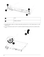
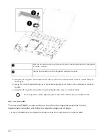


3. Plug the power cables into the power supplies and reinstall the power cable retainers.
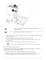
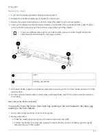
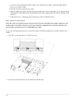
4. Insert the controller module into the chassis:
a. Ensure the latching mechanism arms are locked in the fully extended position.
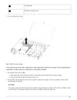
b. Using both hands, align and gently slide the controller module into the latching mechanism arms until it
stops.
c. Place your index fingers through the finger holes from the inside of the latching mechanism.
d. Press your thumbs down on the orange tabs on top of the latching mechanism and gently push the
controller module over the stop.
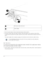
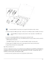
e. Release your thumbs from the top of the latching mechanisms and continue pushing until the latching
mechanisms snap into place.
The controller module begins to boot as soon as it is fully seated in the chassis. Be prepared to
interrupt the boot process.
The controller module should be fully inserted and flush with the edges of the chassis.
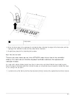
5. Repeat the preceding steps to install the second controller into the new chassis.
Complete the restoration and replacement process - AFF A250
Step 1: Verify and set the HA state of the chassis
You must verify the HA state of the chassis, and, if necessary, update the state to match
your system configuration.
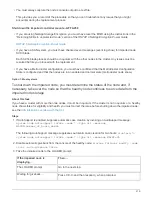
1. In Maintenance mode, from either controller module, display the HA state of the local controller module and
chassis:
ha-config show
The HA state should be the same for all components.
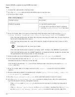
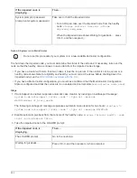
2. If the displayed system state for the chassis does not match your system configuration:
a. Set the HA state for the chassis:
ha-config modify chassis
HA-state
The value for HA-state can be one of the following:
▪
ha
▪
mcc
▪
mccip
▪
non-ha
b. Confirm that the setting has changed:
ha-config show
3. If you have not already done so, recable the rest of your system.
4. Reinstall the bezel on the front of the system.
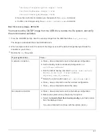
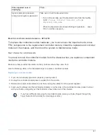
Step 2: Run diagnostics
After you have replaced a component in your system, you should run diagnostic tests on
that component.
217
Summary of Contents for AFF A700
Page 4: ...AFF and FAS System Documentation 1...
Page 208: ...3 Close the controller module cover and tighten the thumbscrew 205...
Page 248: ...2 Close the controller module cover and tighten the thumbscrew 245...
Page 308: ...Power supply Cam handle release latch Power and Fault LEDs Cam handle 305...
Page 381: ...Power supply Cam handle release latch Power and Fault LEDs Cam handle 378...
Page 437: ...1 Locate the DIMMs on your controller module 434...
Page 605: ...602...
Page 1117: ...3 Close the controller module cover and tighten the thumbscrew 1114...
Page 1157: ...2 Close the controller module cover and tighten the thumbscrew 1154...
Page 1228: ...Power supply Cam handle release latch Power and Fault LEDs Cam handle 1225...
Page 1300: ...Power supply Cam handle release latch Power and Fault LEDs Cam handle 1297...
Page 1462: ...Installing SuperRail to round hole four post rack 1459...
Page 1602: ...1599...
Page 1630: ...1627...
Page 1634: ...Orange ring on horizontal bracket Cable chain 1631...
Page 1645: ...Guide rail 1642...
Page 1669: ...Attention LED light on 1666...