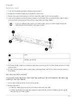
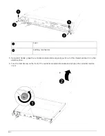
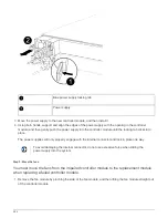
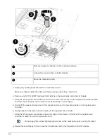

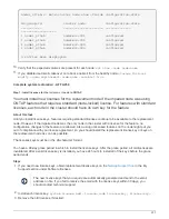
Blue power supply locking tab
Power supply
3. Move the power supply to the new controller module, and then install it.
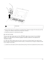
4. Using both hands, support and align the edges of the power supply with the opening in the controller
module, and then gently push the power supply into the controller module until the locking tab clicks into
place.
The power supplies will only properly engage with the internal connector and lock in place one way.
To avoid damaging the internal connector, do not use excessive force when sliding the
power supply into the system.
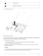
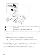
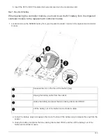
Step 3: Move the fans
You must move the fans from the impaired controller module to the replacement module
when replacing a failed controller module.
1. Remove the fan module by pinching the side of the fan module, and then lifting the fan module straight out
of the controller module.
224
Summary of Contents for AFF A700
Page 4: ...AFF and FAS System Documentation 1...
Page 208: ...3 Close the controller module cover and tighten the thumbscrew 205...
Page 248: ...2 Close the controller module cover and tighten the thumbscrew 245...
Page 308: ...Power supply Cam handle release latch Power and Fault LEDs Cam handle 305...
Page 381: ...Power supply Cam handle release latch Power and Fault LEDs Cam handle 378...
Page 437: ...1 Locate the DIMMs on your controller module 434...
Page 605: ...602...
Page 1117: ...3 Close the controller module cover and tighten the thumbscrew 1114...
Page 1157: ...2 Close the controller module cover and tighten the thumbscrew 1154...
Page 1228: ...Power supply Cam handle release latch Power and Fault LEDs Cam handle 1225...
Page 1300: ...Power supply Cam handle release latch Power and Fault LEDs Cam handle 1297...
Page 1462: ...Installing SuperRail to round hole four post rack 1459...
Page 1602: ...1599...
Page 1630: ...1627...
Page 1634: ...Orange ring on horizontal bracket Cable chain 1631...
Page 1645: ...Guide rail 1642...
Page 1669: ...Attention LED light on 1666...