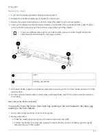
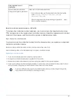
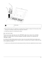
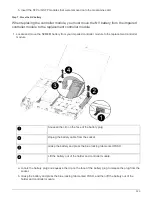

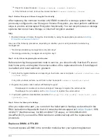
Fan module
2. Move the fan module to the replacement controller module, and align the edges of the fan module with the
opening in the controller module, and then slide the fan module in.
3. Repeat these steps for the remaining fan modules.
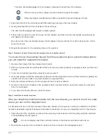
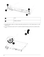
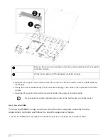
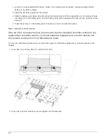
Step 4: Move the boot media
There is one boot media device in the AFF A250 under the air duct in the controller
module. You must move it from the impaired controller module to the replacement
controller module.
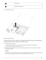
You need a #1 magnetic Phillips head screw driver to remove the screw that holds the boot media in-place.
Due to the space constraints within the controller module, you should also have a magnet to transfer the screw
on to so that you do not lose it.
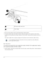
1. Locate and move the boot media from the impaired controller module to the replacement controller module.
225
Summary of Contents for AFF A700
Page 4: ...AFF and FAS System Documentation 1...
Page 208: ...3 Close the controller module cover and tighten the thumbscrew 205...
Page 248: ...2 Close the controller module cover and tighten the thumbscrew 245...
Page 308: ...Power supply Cam handle release latch Power and Fault LEDs Cam handle 305...
Page 381: ...Power supply Cam handle release latch Power and Fault LEDs Cam handle 378...
Page 437: ...1 Locate the DIMMs on your controller module 434...
Page 605: ...602...
Page 1117: ...3 Close the controller module cover and tighten the thumbscrew 1114...
Page 1157: ...2 Close the controller module cover and tighten the thumbscrew 1154...
Page 1228: ...Power supply Cam handle release latch Power and Fault LEDs Cam handle 1225...
Page 1300: ...Power supply Cam handle release latch Power and Fault LEDs Cam handle 1297...
Page 1462: ...Installing SuperRail to round hole four post rack 1459...
Page 1602: ...1599...
Page 1630: ...1627...
Page 1634: ...Orange ring on horizontal bracket Cable chain 1631...
Page 1645: ...Guide rail 1642...
Page 1669: ...Attention LED light on 1666...