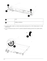
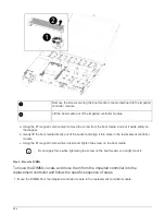
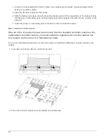

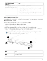
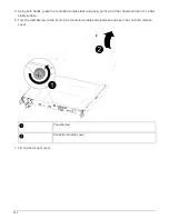
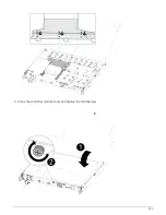

e. Release your thumbs from the top of the latching mechanisms and continue pushing until the latching
mechanisms snap into place.
The controller module begins to boot as soon as it is fully seated in the chassis. Be prepared to
interrupt the boot process.
The controller module should be fully inserted and flush with the edges of the chassis.
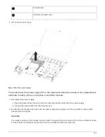
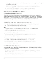
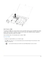
Restore and verify the system configuration - AFF A250
Set and verify system time after replacing the controller
You should check the time and date on the replacement controller module against the
healthy controller module in an HA pair, or against a reliable time server in a stand-alone
configuration. If the time and date do not match, you must reset them on the replacement
controller module to prevent possible outages on clients due to time differences.
About this task
It is important that you apply the commands in the steps on the correct systems:
• The
replacement
node is the new node that replaced the impaired node as part of this procedure.
• The
healthy
node is the HA partner of the
replacement
node
Steps
1. If the
replacement
node is not at the LOADER prompt, halt the system to the LOADER prompt.
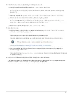
2. On the healthy node, check the system time:
show date
The date and time are given in GMT.
3. At the LOADER prompt, check the date and time on the
replacement
node:
show date
The date and time are given in GMT.
4. If necessary, set the date in GMT on the replacement node:
set date
mm/dd/yyyy
5. If necessary, set the time in GMT on the replacement node:
set time
hh:mm:ss
6. At the LOADER prompt, confirm the date and time on the
replacement
node:
show date
The date and time are given in GMT.
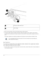
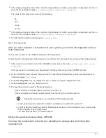
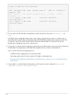
Step 2: Verify and set the HA state of the controller
You must verify the
HA
state of the controller module and, if necessary, update the state
to match your system configuration.
1. In Maintenance mode from the new controller module, verify that all components display the same
HA
state:
ha-config show
The HA state should be the same for all components.
232
Summary of Contents for AFF A700
Page 4: ...AFF and FAS System Documentation 1...
Page 208: ...3 Close the controller module cover and tighten the thumbscrew 205...
Page 248: ...2 Close the controller module cover and tighten the thumbscrew 245...
Page 308: ...Power supply Cam handle release latch Power and Fault LEDs Cam handle 305...
Page 381: ...Power supply Cam handle release latch Power and Fault LEDs Cam handle 378...
Page 437: ...1 Locate the DIMMs on your controller module 434...
Page 605: ...602...
Page 1117: ...3 Close the controller module cover and tighten the thumbscrew 1114...
Page 1157: ...2 Close the controller module cover and tighten the thumbscrew 1154...
Page 1228: ...Power supply Cam handle release latch Power and Fault LEDs Cam handle 1225...
Page 1300: ...Power supply Cam handle release latch Power and Fault LEDs Cam handle 1297...
Page 1462: ...Installing SuperRail to round hole four post rack 1459...
Page 1602: ...1599...
Page 1630: ...1627...
Page 1634: ...Orange ring on horizontal bracket Cable chain 1631...
Page 1645: ...Guide rail 1642...
Page 1669: ...Attention LED light on 1666...


