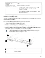
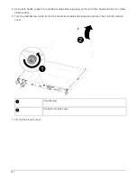
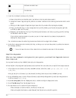

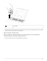
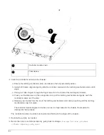


Controller module cover
Thumbscrew
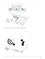
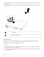
3. Insert the controller module into the chassis:
a. Ensure the latching mechanism arms are locked in the fully extended position.
b. Using both hands, align and gently slide the controller module into the latching mechanism arms until it
stops.
c. Place your index fingers through the finger holes from the inside of the latching mechanism.
d. Press your thumbs down on the orange tabs on top of the latching mechanism and gently push the
controller module over the stop.
e. Release your thumbs from the top of the latching mechanisms and continue pushing until the latching
mechanisms snap into place.
The controller module begins to boot as soon as it is fully seated in the chassis. Be prepared to
interrupt the boot process.
The controller module should be fully inserted and flush with the edges of the chassis.
4. Cable the management and console ports only, so that you can access the system to perform the tasks in
the following sections.
You will connect the rest of the cables to the controller module later in this procedure.
Step 5: Run diagnostics
After you have replaced a component in your system, you should run diagnostic tests on
that component.
Your system must be at the LOADER prompt to start diagnostics.
All commands in the diagnostic procedures are issued from the node where the component is being replaced.
1. If the node to be serviced is not at the LOADER prompt, reboot the node:
system node halt -node
node_name
After you issue the command, you should wait until the system stops at the LOADER prompt.
2. At the LOADER prompt, access the special drivers specifically designed for system-level diagnostics to
function properly:
boot_diags
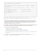
3. Select
Scan System
from the displayed menu to enable running the diagnostics tests.
4. Select
Test Memory
from the displayed menu.
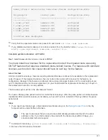
5. Proceed based on the result of the preceding step:
◦
If the test failed, correct the failure, and then rerun the test.
◦
If the test reported no failures, select Reboot from the menu to reboot the system.
246
Summary of Contents for AFF A700
Page 4: ...AFF and FAS System Documentation 1...
Page 208: ...3 Close the controller module cover and tighten the thumbscrew 205...
Page 248: ...2 Close the controller module cover and tighten the thumbscrew 245...
Page 308: ...Power supply Cam handle release latch Power and Fault LEDs Cam handle 305...
Page 381: ...Power supply Cam handle release latch Power and Fault LEDs Cam handle 378...
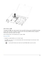
Page 437: ...1 Locate the DIMMs on your controller module 434...
Page 605: ...602...
Page 1117: ...3 Close the controller module cover and tighten the thumbscrew 1114...
Page 1157: ...2 Close the controller module cover and tighten the thumbscrew 1154...
Page 1228: ...Power supply Cam handle release latch Power and Fault LEDs Cam handle 1225...
Page 1300: ...Power supply Cam handle release latch Power and Fault LEDs Cam handle 1297...
Page 1462: ...Installing SuperRail to round hole four post rack 1459...
Page 1602: ...1599...
Page 1630: ...1627...
Page 1634: ...Orange ring on horizontal bracket Cable chain 1631...
Page 1645: ...Guide rail 1642...
Page 1669: ...Attention LED light on 1666...