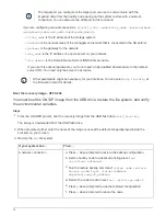

Warning: Rebooting or halting node
"node_name" in an HA-enabled cluster may result in client disruption or
data access
failure. To ensure continuity of service, use the "storage
failover takeover" command. Are you sure you want to halt node
"node_name"? {y|n}:
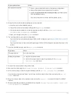
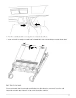
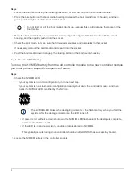
You must perform a clean system shutdown before replacing the chassis to avoid losing
unwritten data in the nonvolatile memory (NVMEM). If the NVMEM LED is flashing, there is
content in the NVMEM that has not been saved to disk. You need to reboot the node and
start from the beginning of this procedure. If repeated attempts to cleanly shut down the
node fail, be aware that you might lose any data that was not saved to disk.
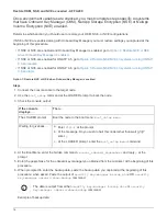
3. Where applicable, halt the second node to avoid a possible quorum error message in an HA pair
configuration:
system node halt -node second_node_name -ignore-quorum-warnings true
Move and replace hardware - AFF A200
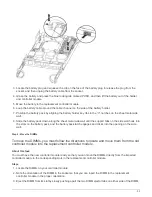
Step 1: Move the power supply
Move the power supply from the old chassis to the replacement chassis.
Steps
1. If you are not already grounded, properly ground yourself.
2. Turn off the power supply and disconnect the power cables:
a. Turn off the power switch on the power supply.
b. Open the power cable retainer, and then unplug the power cable from the power supply.
c. Unplug the power cable from the power source.
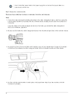
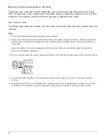
3. Squeeze the latch on the power supply cam handle, and then open the cam handle to fully release the
power supply from the mid plane.
4. Use the cam handle to slide the power supply out of the system.
CAUTION:
When removing a power supply, always use two hands to support its weight.
5. Repeat the preceding steps for any remaining power supplies.
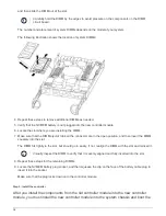
6. Using both hands, support and align the edges of the power supply with the opening in the system chassis,
and then gently push the power supply into the chassis using the cam handle.
The power supplies are keyed and can only be installed one way.
Do not use excessive force when sliding the power supply into the system. You can damage
the connector.
7. Close the cam handle so that the latch clicks into the locked position and the power supply is fully seated.
8. Reconnect the power cable and secure it to the power supply using the power cable locking mechanism.
23
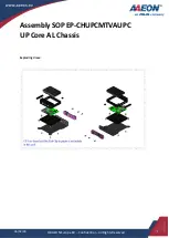
Summary of Contents for AFF A700
Page 4: ...AFF and FAS System Documentation 1...
Page 208: ...3 Close the controller module cover and tighten the thumbscrew 205...
Page 248: ...2 Close the controller module cover and tighten the thumbscrew 245...
Page 308: ...Power supply Cam handle release latch Power and Fault LEDs Cam handle 305...
Page 381: ...Power supply Cam handle release latch Power and Fault LEDs Cam handle 378...
Page 437: ...1 Locate the DIMMs on your controller module 434...
Page 605: ...602...
Page 1117: ...3 Close the controller module cover and tighten the thumbscrew 1114...
Page 1157: ...2 Close the controller module cover and tighten the thumbscrew 1154...
Page 1228: ...Power supply Cam handle release latch Power and Fault LEDs Cam handle 1225...
Page 1300: ...Power supply Cam handle release latch Power and Fault LEDs Cam handle 1297...
Page 1462: ...Installing SuperRail to round hole four post rack 1459...
Page 1602: ...1599...
Page 1630: ...1627...
Page 1634: ...Orange ring on horizontal bracket Cable chain 1631...
Page 1645: ...Guide rail 1642...
Page 1669: ...Attention LED light on 1666...