
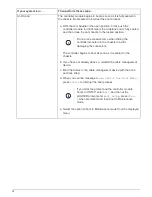

If your system is in…
Then perform these steps…
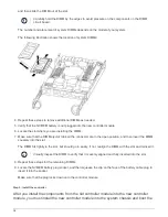
A stand-alone configuration
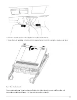
a. With the cam handle in the open position, firmly push the
controller module in until it meets the midplane and is fully seated,
and then close the cam handle to the locked position.
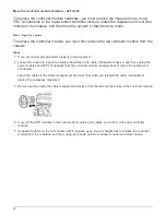
Do not use excessive force when sliding the
controller module into the chassis to avoid
damaging the connectors.
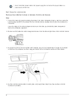
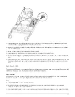
b. If you have not already done so, reinstall the cable management
device.
c. Bind the cables to the cable management device with the hook
and loop strap.
d. Reinstall the blanking panel and then go to the next step.
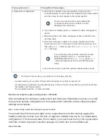
5. Connect the power supplies to different power sources, and then turn them on.
6. Boot each node to Maintenance mode:
a. As each node starts the booting, press
Ctrl-C
to interrupt the boot process when you see the
message
Press Ctrl-C for Boot Menu
.
If you miss the prompt and the controller modules boot to ONTAP, enter
halt
, and then
at the LOADER prompt enter
boot_ontap
, press
Ctrl-C
when prompted, and then
repeat this step.
b. From the boot menu, select the option for Maintenance mode.
Restoring and verifying the configuration - AFF A200
Step 1: Verifying and setting the HA state of the chassis
You must verify the HA state of the chassis, and, if necessary, update the state to match
your system configuration.
Steps
1. In Maintenance mode, from either controller module, display the HA state of the local controller module and
chassis:
ha-config show
The HA state should be the same for all components.
2. If the displayed system state for the chassis does not match your system configuration:
a. Set the HA state for the chassis:
ha-config modify chassis
HA-state
The value for HA-state can be one of the following:
▪
ha
▪
non-ha
b. Confirm that the setting has changed:
ha-config show
27
Summary of Contents for AFF A700
Page 4: ...AFF and FAS System Documentation 1...
Page 208: ...3 Close the controller module cover and tighten the thumbscrew 205...
Page 248: ...2 Close the controller module cover and tighten the thumbscrew 245...
Page 308: ...Power supply Cam handle release latch Power and Fault LEDs Cam handle 305...
Page 381: ...Power supply Cam handle release latch Power and Fault LEDs Cam handle 378...
Page 437: ...1 Locate the DIMMs on your controller module 434...
Page 605: ...602...
Page 1117: ...3 Close the controller module cover and tighten the thumbscrew 1114...
Page 1157: ...2 Close the controller module cover and tighten the thumbscrew 1154...
Page 1228: ...Power supply Cam handle release latch Power and Fault LEDs Cam handle 1225...
Page 1300: ...Power supply Cam handle release latch Power and Fault LEDs Cam handle 1297...
Page 1462: ...Installing SuperRail to round hole four post rack 1459...
Page 1602: ...1599...
Page 1630: ...1627...
Page 1634: ...Orange ring on horizontal bracket Cable chain 1631...
Page 1645: ...Guide rail 1642...
Page 1669: ...Attention LED light on 1666...


