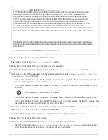
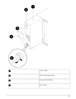
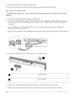
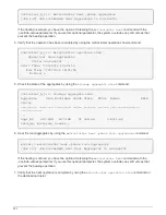

Power cable locking mechanism
4. Use the cam handle to slide the power supply out of the system.
CAUTION:
When removing a power supply, always use two hands to support its weight.
5. Repeat the preceding steps for any remaining power supplies.
6. Using both hands, support and align the edges of the power supply with the opening in the system chassis,
and then gently push the power supply into the chassis using the cam handle.
The power supplies are keyed and can only be installed one way.
Do not use excessive force when sliding the power supply into the system. You can damage
the connector.
7. Push firmly on the power supply cam handle to seat it all the way into the chassis, and then push the cam
handle to the closed position, making sure that the cam handle release latch clicks into its locked position.
8. Reconnect the power cable and secure it to the power supply using the power cable locking mechanism.
Only connect the power cable to the power supply. Do not connect the power cable to a
power source at this time.
Step 2: Move a fan
Moving out a fan module when replacing the chassis involves a specific sequence of
tasks.
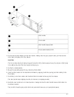
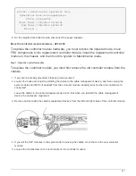
1. Remove the bezel (if necessary) with two hands, by grasping the openings on each side of the bezel, and
then pulling it toward you until the bezel releases from the ball studs on the chassis frame.
2. Press down the release latch on the fan module cam handle, and then pull the cam handle downward.
The fan module moves a little bit away from the chassis.
306
Summary of Contents for AFF A700
Page 4: ...AFF and FAS System Documentation 1...
Page 208: ...3 Close the controller module cover and tighten the thumbscrew 205...
Page 248: ...2 Close the controller module cover and tighten the thumbscrew 245...
Page 308: ...Power supply Cam handle release latch Power and Fault LEDs Cam handle 305...
Page 381: ...Power supply Cam handle release latch Power and Fault LEDs Cam handle 378...
Page 437: ...1 Locate the DIMMs on your controller module 434...
Page 605: ...602...
Page 1117: ...3 Close the controller module cover and tighten the thumbscrew 1114...
Page 1157: ...2 Close the controller module cover and tighten the thumbscrew 1154...
Page 1228: ...Power supply Cam handle release latch Power and Fault LEDs Cam handle 1225...
Page 1300: ...Power supply Cam handle release latch Power and Fault LEDs Cam handle 1297...
Page 1462: ...Installing SuperRail to round hole four post rack 1459...
Page 1602: ...1599...
Page 1630: ...1627...
Page 1634: ...Orange ring on horizontal bracket Cable chain 1631...
Page 1645: ...Guide rail 1642...
Page 1669: ...Attention LED light on 1666...


