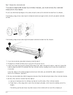
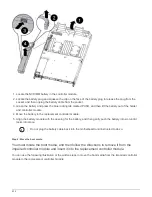
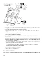
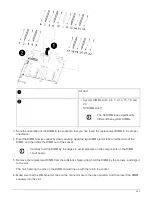

Air duct
• System DIMMs slots: 2,4, 7, 9, 13, 15, 18, and
20
• NVDIMM slot: 11
The NVDIMM looks significantly
different than system DIMMs.
2. Note the orientation of the DIMM in the socket so that you can insert the DIMM in the replacement
controller module in the proper orientation.
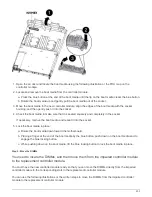
3. Verify that the NVDIMM battery is not plugged into the new controller module.
4. Move the DIMMs from the impaired controller module to the replacement controller module:
Make sure that you install the each DIMM into the same slot it occupied in the impaired
controller module.
a. Eject the DIMM from its slot by slowly pushing apart the DIMM ejector tabs on either side of the DIMM,
and then slide the DIMM out of the slot.
Carefully hold the DIMM by the edges to avoid pressure on the components on the
DIMM circuit board.
b. Locate the corresponding DIMM slot on the replacement controller module.
c. Make sure that the DIMM ejector tabs on the DIMM socket are in the open position, and then insert the
DIMM squarely into the socket.
The DIMMs fit tightly in the socket, but should go in easily. If not, realign the DIMM with the socket and
reinsert it.
d. Visually inspect the DIMM to verify that it is evenly aligned and fully inserted into the socket.
e. Repeat these substeps for the remaining DIMMs.
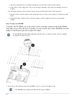
5. Plug the NVDIMM battery into the motherboard.
Make sure that the plug locks down onto the controller module.
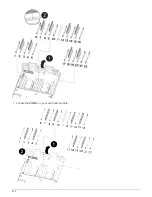
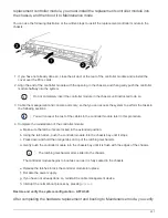
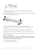
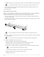
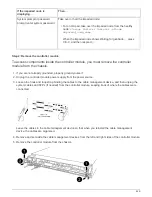
Step 6: Move the PCIe risers
You must move the PCIe risers, with the PCIe cards installed in them, from the impaired
controller module to the replacement controller module.
You can use the following illustration or the written steps to move the PCIe risers from the impaired controller
module to the replacement controller module.
435
Summary of Contents for AFF A700
Page 4: ...AFF and FAS System Documentation 1...
Page 208: ...3 Close the controller module cover and tighten the thumbscrew 205...
Page 248: ...2 Close the controller module cover and tighten the thumbscrew 245...
Page 308: ...Power supply Cam handle release latch Power and Fault LEDs Cam handle 305...
Page 381: ...Power supply Cam handle release latch Power and Fault LEDs Cam handle 378...
Page 437: ...1 Locate the DIMMs on your controller module 434...
Page 605: ...602...
Page 1117: ...3 Close the controller module cover and tighten the thumbscrew 1114...
Page 1157: ...2 Close the controller module cover and tighten the thumbscrew 1154...
Page 1228: ...Power supply Cam handle release latch Power and Fault LEDs Cam handle 1225...
Page 1300: ...Power supply Cam handle release latch Power and Fault LEDs Cam handle 1297...
Page 1462: ...Installing SuperRail to round hole four post rack 1459...
Page 1602: ...1599...
Page 1630: ...1627...
Page 1634: ...Orange ring on horizontal bracket Cable chain 1631...
Page 1645: ...Guide rail 1642...
Page 1669: ...Attention LED light on 1666...