

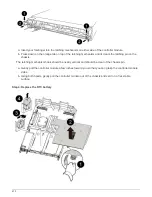
d. Reinstall the PCIe riser cover on the controller module.
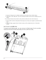
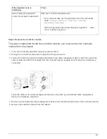
Sep 4: Install the controller module
After you have replaced the component in the controller module, you must re-install the
controller module into the chassis, and then boot it to Maintenance mode.
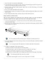
1. If you have not already done so, close the air duct at the rear of the controller module and reinstall the
cover over the PCIe cards.
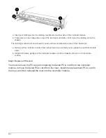
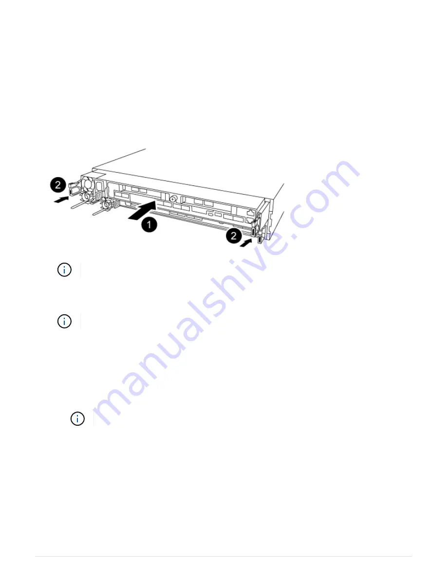
2. Align the end of the controller module with the opening in the chassis, and then gently push the controller
module halfway into the system.
Do not completely insert the controller module in the chassis until instructed to do so.
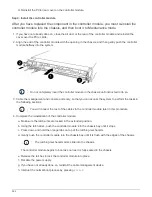
3. Cable the management and console ports only, so that you can access the system to perform the tasks in
the following sections.
You will connect the rest of the cables to the controller module later in this procedure.
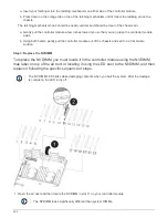
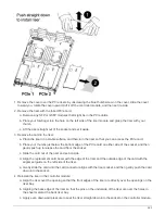
4. Complete the reinstallation of the controller module:
a. Make sure the latch arms are locked in the extended position.
b. Using the latch arms, push the controller module into the chassis bay until it stops.
c. Press down and hold the orange tabs on top of the latching mechanism.
d. Gently push the controller module into the chassis bay until it is flush with the edges of the chassis.
The latching mechanism arms slide into the chassis.
The controller module begins to boot as soon as it is fully seated in the chassis.
e. Release the latches to lock the controller module into place.
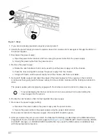
f. Recable the power supply.
g. If you have not already done so, reinstall the cable management device.
h. Interrupt the normal boot process by pressing
Ctrl-C
.
464
Summary of Contents for AFF A700
Page 4: ...AFF and FAS System Documentation 1...
Page 208: ...3 Close the controller module cover and tighten the thumbscrew 205...
Page 248: ...2 Close the controller module cover and tighten the thumbscrew 245...
Page 308: ...Power supply Cam handle release latch Power and Fault LEDs Cam handle 305...
Page 381: ...Power supply Cam handle release latch Power and Fault LEDs Cam handle 378...
Page 437: ...1 Locate the DIMMs on your controller module 434...
Page 605: ...602...
Page 1117: ...3 Close the controller module cover and tighten the thumbscrew 1114...
Page 1157: ...2 Close the controller module cover and tighten the thumbscrew 1154...
Page 1228: ...Power supply Cam handle release latch Power and Fault LEDs Cam handle 1225...
Page 1300: ...Power supply Cam handle release latch Power and Fault LEDs Cam handle 1297...
Page 1462: ...Installing SuperRail to round hole four post rack 1459...
Page 1602: ...1599...
Page 1630: ...1627...
Page 1634: ...Orange ring on horizontal bracket Cable chain 1631...
Page 1645: ...Guide rail 1642...
Page 1669: ...Attention LED light on 1666...