
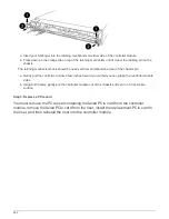
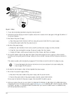
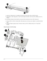
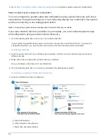

1. Remove the PCIe cover.
a. Unscrew the blue thumbscrew located above the onboard ports at the back of the controller module.
b. Slide the cover toward you and rotate the cover upward.
c. Remove the cover and set it aside.
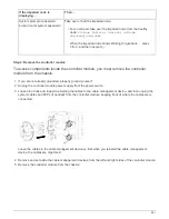
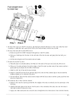
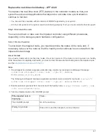
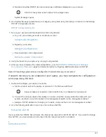
2. Locate, remove, and then replace the RTC battery:
a. Using the FRU map, locate the RTC battery on the controller module.
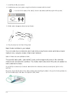
b. Gently push the battery away from the holder, rotate it away from the holder, and then lift it out of the
holder.
Note the polarity of the battery as you remove it from the holder. The battery is marked
with a plus sign and must be positioned in the holder correctly. A plus sign near the
holder tells you how the battery should be positioned.
c. Remove the replacement battery from the antistatic shipping bag.
d. Note the polarity of the RTC battery, and then insert it into the holder by tilting the battery at an angle
and pushing down.
3. Visually inspect the battery to make sure that it is completely installed into the holder and that the polarity is
correct.
4. Reinstall the PCIe cover on the controller module.
Step 5: Reinstall the controller module and setting time/date after RTC battery replacement
After you replace a component within the controller module, you must reinstall the
controller module in the system chassis, reset the time and date on the controller, and
then boot it.
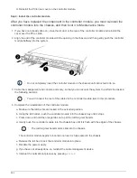
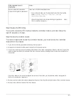
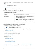
1. If you have not already done so, close the air duct or controller module cover.
2. Align the end of the controller module with the opening in the chassis, and then gently push the controller
module halfway into the system.
Do not completely insert the controller module in the chassis until instructed to do so.
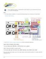
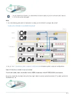
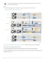
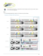
3. Recable the system, as needed.
If you removed the media converters (QSFPs or SFPs), remember to reinstall them if you are using fiber
optic cables.
4. If the power supplies were unplugged, plug them back in and reinstall the power cable retainers.
5. Complete the reinstallation of the controller module:
a. Make sure the latch arms are locked in the extended position.
b. Using the latch arms, push the controller module into the chassis bay until it stops.
Do not push down on the latching mechanism at the top of the latch arms. Doing so with
raise the locking mechanism and prohibit sliding the controller module into the chassis.
c. Press down and hold the orange tabs on top of the latching mechanism.
471
Summary of Contents for AFF A700
Page 4: ...AFF and FAS System Documentation 1...
Page 208: ...3 Close the controller module cover and tighten the thumbscrew 205...
Page 248: ...2 Close the controller module cover and tighten the thumbscrew 245...
Page 308: ...Power supply Cam handle release latch Power and Fault LEDs Cam handle 305...
Page 381: ...Power supply Cam handle release latch Power and Fault LEDs Cam handle 378...
Page 437: ...1 Locate the DIMMs on your controller module 434...
Page 605: ...602...
Page 1117: ...3 Close the controller module cover and tighten the thumbscrew 1114...
Page 1157: ...2 Close the controller module cover and tighten the thumbscrew 1154...
Page 1228: ...Power supply Cam handle release latch Power and Fault LEDs Cam handle 1225...
Page 1300: ...Power supply Cam handle release latch Power and Fault LEDs Cam handle 1297...
Page 1462: ...Installing SuperRail to round hole four post rack 1459...
Page 1602: ...1599...
Page 1630: ...1627...
Page 1634: ...Orange ring on horizontal bracket Cable chain 1631...
Page 1645: ...Guide rail 1642...
Page 1669: ...Attention LED light on 1666...