
Step 3: Transfer the boot image to the boot media
The replacement boot media that you installed does not have a boot image, so you need
to transfer a boot image using a USB flash drive.
Before you begin
• You must have a USB flash drive, formatted to MBR/FAT32, with at least 4GB capacity
• A copy of the same image version of ONTAP as what the impaired controller was running. You can
download the appropriate image from the Downloads section on the NetApp Support Site
◦
If NVE is enabled, download the image with NetApp Volume Encryption, as indicated in the download
button.
◦
If NVE is not enabled, download the image without NetApp Volume Encryption, as indicated in the
download button.
• If your system is an HA pair, you must have a network connection.
• If your system is a stand-alone system you do not need a network connection, but you must perform an
additional reboot when restoring the
var
file system.
Steps
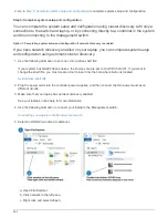
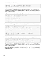
1. Download and copy the appropriate service image from the NetApp Support Site to the USB flash drive.
a. Download the service image to your work space on your laptop.
b. Unzip the service image.
If you are extracting the contents using Windows, do not use WinZip to extract the
netboot image. Use another extraction tool, such as 7-Zip or WinRAR.
There are two folders in the unzipped service image file:
▪
boot
▪
efi
c. Copy the
efi
folder to the top directory on the USB flash drive.
The USB flash drive should have the efi folder and the same Service Image (BIOS) version of what the
impaired controller is running.
d. Remove the USB flash drive from your laptop.
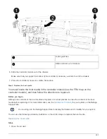
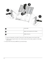
2. If you have not already done so, close the air duct.
3. Align the end of the controller module with the opening in the chassis, and then gently push the controller
module halfway into the system.
4. Reinstall the cable management device and recable the system, as needed.
When recabling, remember to reinstall the media converters (SFPs or QSFPs) if they were removed.
5. Plug the power cable into the power supply and reinstall the power cable retainer.
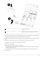
6. Insert the USB flash drive into the USB slot on the controller module.
Make sure that you install the USB flash drive in the slot labeled for USB devices, and not in the USB
console port.
496
Summary of Contents for AFF A700
Page 4: ...AFF and FAS System Documentation 1...
Page 208: ...3 Close the controller module cover and tighten the thumbscrew 205...
Page 248: ...2 Close the controller module cover and tighten the thumbscrew 245...
Page 308: ...Power supply Cam handle release latch Power and Fault LEDs Cam handle 305...
Page 381: ...Power supply Cam handle release latch Power and Fault LEDs Cam handle 378...
Page 437: ...1 Locate the DIMMs on your controller module 434...
Page 605: ...602...
Page 1117: ...3 Close the controller module cover and tighten the thumbscrew 1114...
Page 1157: ...2 Close the controller module cover and tighten the thumbscrew 1154...
Page 1228: ...Power supply Cam handle release latch Power and Fault LEDs Cam handle 1225...
Page 1300: ...Power supply Cam handle release latch Power and Fault LEDs Cam handle 1297...
Page 1462: ...Installing SuperRail to round hole four post rack 1459...
Page 1602: ...1599...
Page 1630: ...1627...
Page 1634: ...Orange ring on horizontal bracket Cable chain 1631...
Page 1645: ...Guide rail 1642...
Page 1669: ...Attention LED light on 1666...


